


Rebuilding the Walbro WG & WB carburetors part 2
by Had Robinson
updated September 16, 2023
Note: the Walbro WG and the Husqvarna 503134701 are identical except that the latter has the main jet pressed in. The Walbro WB and the Walbro MPE090 have identical main parts.
Note: some newer paramotors have the Tillotson HT-21A substituted for the WG-8. Repair kit: RK-28-HS, Diaphragms only: DG-7-HS, tuned very much like the WG but the high speed fuel mixture is adjustable within a safe range. Pop-off: 25 psi Rest: 13 psi Metering lever height: 1.80mm
by Had Robinson
updated June 7, 2023
- Rebuild the carburetor at least once a year because the flexible material inside ages whether it is used or no. Ethanol gasoline will require more frequent rebuilds. If the idle is erratic, difficult to set, or it will not idle, this is your cue to rebuild. If you do not have a CHT, waiting too late can cause engine overheating.
- The instructions on this page are for the WG but can be used for the Tillotson and other similar Walbro models, like the WB and the new MPE090.
- If your clutched engine engages at idle (< 2,500 RPM), it will be difficult or impossible to adjust the idle properly. Fix this first.
- NEVER APPLY COMPRESSED AIR TO THE CARBURETOR INLET. THIS WILLWRECK THE CARBURETOR!
Preliminaries
- Learn the parts of a Walbro carburetor – Study this diagram of the WG. Go to the WB/MPE090
page for
specific instructions and a parts diagram for that carburetor.
These diagrams are of generic carburetors. All important parts are numbered and labeled. Some parts may be slightly different in shape. Some parts are unique to a particular series. The metering lever diaphragm and the fuel pump cover designs vary. Note: the WG diagram shows a power needle (part# 40). This does not exist on any WG carburetors found on paramotors. A fixed main jet is always used, instead. The diagrams are from Walbro are 20-30 years old. Walbro does *NOT* support ANY aviation use of their carburetors. The new Tillotson HT series carburetor has an adjustable main jet and is a fairly well-made clone of the WG.
It is helpful if you understand how a diaphragm carburetor works. ZAMA's technical guide is the best there is because it is short, simple, and concise. It is functionally identical to the Walbro and Tillotson HT. It is decades newer and has more information than Walbro's technical guides on how diaphragm carburetors work. The guides are very technical and not useful to paramotor pilots. - Ignition system check – Before attempting a carburetor tune up or rebuild, check the ignition system first to see if
there are any issues. Replace the spark plug with a new one, properly gapped. If your spark plug secondary wire is "open" (broken internally), you are wasting your time tuning up the carburetor.
- Coil gap – If the coil has never been replaced, this step may be skipped. The coil gap is frequently adjusted incorrectly. This page gives the
instructions on how to check/replace the coil. If a professional
replaces the coil, print out the page on the coil and give it
to him. He will need the information. Note: it is a good idea (but not essential) to check the timing if the
coil has been replaced. This is because there may be significant variations in the mounting holes which could affect the timing, although slightly.
- Reed valve body leaks (Top 80, newer Moster 185's, and others that feed the fuel pump pulses through the reed valve body) – If you are having
fuel delivery problems (engine will not start of idle, stalls at full throttle), be sure that the reed valve block screws have been properly torqued down. If the block is even slightly loose, the fuel pump will
not function properly, if at all. I have seen this in many brand new engines.
- Fuel pump pulse passages (including tubing to the engine crankcase) must be carefully checked to be sure there are no obstructions.
ALL ENGINES WITH INTERNAL PULSE PORTS e.g. Top 80, newer Moster 185 – CAUTION When removing the carburetor, always check the torque on the reed valve body screws. If they are loose, the valve body will leak and the fuel pump will not work properly. If they are loose, remove them, clean the screws and holes with brake cleaner, blow dry, and apply blue threadlock and reinstall to the correct torque for your motor. If you have any suspicion that your reed valve is not properly sealed to the crankcase, see the reed valve page for help.
- Check the pickup tube filter in the bottom of the fuel tank to be sure it is not clogged with gel/goo (due to
ethanol fuels). Replace it if in doubt. If you can easily blow through it, all is OK. The pickup tube filter (also called a "clunk") is weighted in order to keep it in the bottom
of the tank. You can use a clogged pickup tube filter by making a hole in it. Eliminating the filter (but not the "clunk") on the
end of the pickup tube is just one more way pilots can eliminate flow restrictions in the fuel system, our most common problem.
- If it has been more than a year replace the inline fuel filter. Do *NOT* purchase fuel filters from an auto parts store because they are almost always of inferior quality. Use a quality paper-type filter, like an OEM factory filter (available from Miniplane-USA). Some auto parts stores may stock (or can order) the WIX #33001 inline fuel filter. It is a superior quality inline fuel filter and is used in some EU vehicles.
Rebuilding the carburetor
WG carburetor ONLY: Do not lose or damage the main jet (part #16). It is not available in most countries. However, we can custom machine jets sizes 098 and larger.
The part numbers given below are for the WG and some may differ from those of the WB. The WB has a circuit plate instead of a Welch plug that covers the idle progression holes.
Special tools needed
-
Southwest Airsports metering lever gauge
If you do not have this simple gauge you will have to have a digital caliper with a special attachment that allows it to work as a depth gauge. - fine Hook & Pick Set (Harbor Freight #93514) or equivalent
- pop-off gauge optional but highly recommended if there are *ANY* problems with the carburetor. Search eBay for "Mikuni - MK-BN PMP - Pop Off Pump Gauge"
- Welch plug removal tool this tool is only needed if the carburetor was used without the inlet filter screen, has a damaged screen, or an improperly seated screen. The WG Welch plug (#18) covers the idle progression holes (IPS). The WB Welch plug (#16) covers some other passages in the carburetor.
- some source of compressed air WARNING: DO NOT EXCEED 25 PSI – HIGHER PRESSURES CAN DAMAGE PARTS OF THE CARBURETOR. NEVER APPLY COMPRESSED AIR TO THE CARBURETOR INLET! Use compressed air to remove exterior debris from the carburetor and the idle progression holes.
- spray carburetor cleaner Note: Do not use fuel injector cleaner. The cleaner must be for carburetors ONLY. Other solvents will destroy the flexible parts of the carburetor. In a pinch, gasoline may be used.
Clean the exterior of the carburetor as well as you can with low pressure air (<25 psi) and cleaner BEFORE removing it from the engine. Use air to remove all traces of cleaner. (If you remove it before cleaning, it is easier to get sand and grit inside things.) Remove the carburetor from the engine.
1. Parts needed Parts are available from Miniplane-USA.
- Purchase a rebuild kit: for the WG part# K12-WG or for the WB part# K10-WB. Note: the rebuild kit will have many extra parts in it.
- Inline fuel filter (ONLY use filters that are rated < 10 microns)
- Metering lever spring – see step #4 below for info on whether it needs to be replaced.
- Pickup tube filter – only necessary if there is any sign of gel/goo on the existing filter
2. Video Watch the Walbro carburetor service video, if you have not already. It has important visual tips for a rebuild. Walbro's metering lever (ML) setting page may be confusing because it refers to the distance from the end of the ML to the surface beneath it. This distance cannot be easily measured so this web site always refers to the distance from the ML to the top surface of the carburetor body which is the reference for setting the ML value. On Walbro's page it discusses a "low value" which equals a "high value" on this web site. The values are opposite.
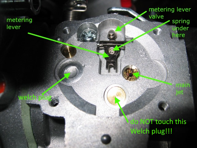
Parts under the WG metering diaphragm cover (the one with the hole in the center)
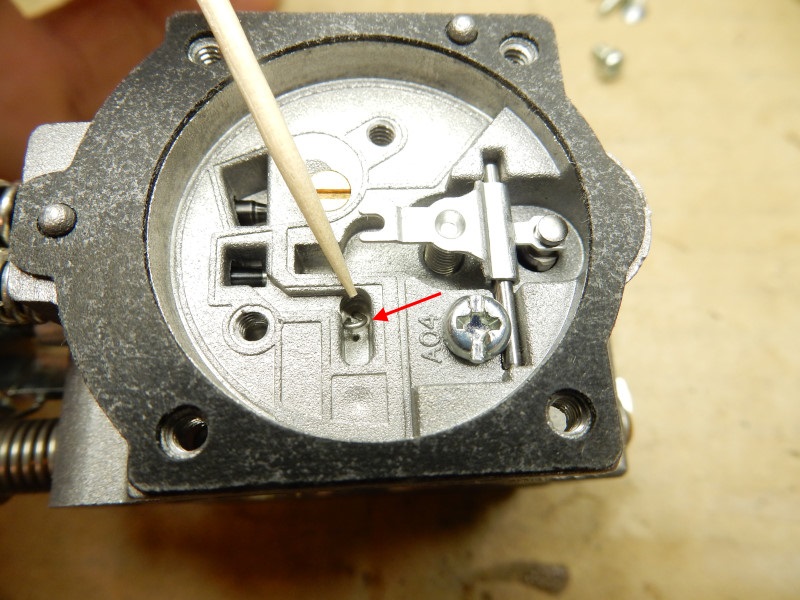
WB carburetor with the metering lever cover and circuit plate removed. The toothpick points to one of the idle progression holes (IPH) which has been plugged to reduce roughness in the midrange. DO NOT ATTEMPT TO REMOVE THE BRASS NOZZLE JET above the IPH. It will be wrecked in the process.
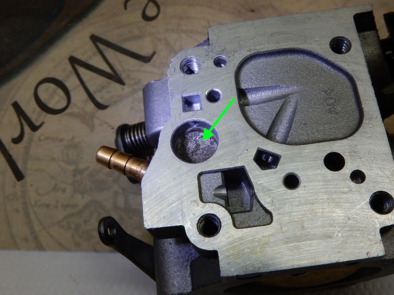
Parts under the WG pump cover. The inlet filter screen (green arrow below) is clogged and needs to be replaced. This motor could not achieve full power. Pilots *must* install the correct type of inline fuel filter. If the inlet filter screen is missing, damaged, or not seated correctly, the Welch plug in the metering lever chamber (other side) must be removed and the distribution hole below it checked for debris.
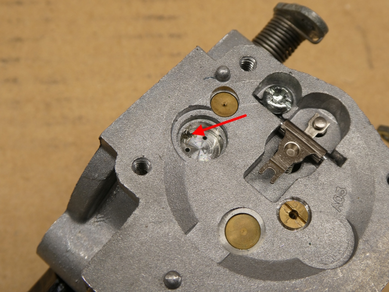
This WG carburetor had a severely clogged idle progression hole because of a damaged and unseated inlet filter screen (#45). The engine that had this carburetor would not idle properly. The Welch plug had to be removed in order to remove the debris. Never use a carburetor with the inlet filter screen removed!
With the help of the service video, disassemble the carburetor:
3. Cover plates Remove both cover plates, all diaphragms, and gaskets. Each is connected to the carburetor body by (4) small screws.
4. Remove the ML Remove the metering lever assembly including the spring by removing the single screw that holds the pivot. Be careful not to lose the screw.
On the WB, remove the circuit plate (#48) which covers the idle progression holes. An aluminum Welch plug covers the idle progression holes on the WG.
DO NOT REMOVE THE BRASS NOZZLE JET ON THE WB! If you attempt it, you will wreck the nozzle.
The WG metering lever spring is 15.0mm long when new, the WB is 13.3mm. If the WG spring measures less than 14.9mm replace it. Replace the WB spring if it is less than 13.2mm. There is not any data yet for the Tillotson.
Here is an ML spring that was modified (see the left end) to shorten it. This would cause the mixture to be richer. Modified springs are never a smart fix for carburetor issues.
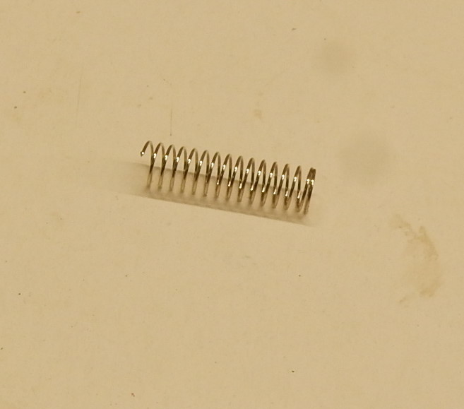
I do not recommend using "miracle springs" or larger main jets to fix fuel pump/fuel supply problems. They are Band-Aids that fail to address the root issue(s).
The life of the spring is dependent on what kind of fuel is used and what climate you fly in. Remember that ethanol fuels attract water and the more humid it is, the more water will be in gasoline containing ethanol. It is so inexpensive to replace the spring and be assured that your pop-off pressure is correct (if you do not have a pop-off gauge).
Defective springs may look the same as new springs but give a different pop-off and rest pressure. A weak spring enriches the air/fuel mixture and engine performance will suffer, especially midrange. A hardened spring (from age and corrosion) will lean the air/fuel mixture and may result in engine overheating. It is not worth saving a few dollars and then overheating your engine. For more information on the ML spring, see the pop-off pressure page.
Checking the pop-off pressure with a gauge may yield a satisfactory value but this does not necessarily mean that the spring is in good condition.
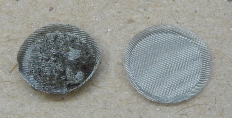
5. Inlet screen NEVER OPERATE THE CARBURETOR WITHOUT THIS SCREEN! Always replace the screen #45 (WG) or #43 (WB). It is located below the pump cover and diaphragm. If the fuel inlet screen has the tiniest bit of debris in it, it means that the inline fuel filter is bad or is not of the correct type. Remove the screen with a fine pick-tool or needle. Sintered bronze inline fuel filters DO NOT FILTER the fine debris which will clog the fuel inlet screen. Do not use this type of filter. Below are (2) filter screens. They are small – about the width of a pencil. The one on the left is almost completely clogged because the pilot had no inline filter installed. A new one is on the right. Note: unbelievably, some owners of paramotor import companies actually believe inline fuel filters are a waste of money!
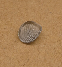
This inlet filter screen had been damaged and was not seated correctly. This allowed to debris to enter the tiny passages in the carburetor and clog them.
6. Examine the carburetor Remove the idle needle #39 (WG) or #40 (WB). On the WB also remove the power needle #41. With a magnifying headset or glass, carefully examine every part, including the carburetor body. If there is any gunk or water drops anywhere, it is a symptom of using gasoline with ethanol, water in the fuel system, and/or old fuel (more than two weeks old). This is warning that you need to check your fuel quality and replace all fuel filters. Read the page on fuel/oil specifications. If you use ethanol fuels, use the correct fuel additives and get an ethanol content tester to be sure your fuel does NOT contain excessive amounts of ethanol or is contaminated by water. Why burn up a $2K engine because you did not check your fuel quality?
7. Clean the inside parts of the carburetor Spray carburetor cleaner through all passages of the completely disassembled carburetor and on the small parts. Do
NOT spray the cleaner on anything but metal. Blow things out with compressed air (<25 PSI). Be certain that all passageways are clear. DO NOT LEAVE ANY TRACES OF THE CLEANER INSIDE THE
CARBURETOR. It must be completely free of ANY solvent. Most cleaners will destroy non-metal parts if they are exposed to the cleaner for any length of time.
Take particular care
to clean the flat surface of the pump side of the carburetor. Put carburetor cleaner on a soft cloth and vigorously clean this surface. Do the same with the pump cover.
8. Welch plug If you discover anything amiss with the inlet filter screen (damaged or missing), the aluminum welch plug
must be removed and the cavity checked and cleaned, if necessary. On the WG also check the idle progression holes that are beneath the
Welch plug. See the Welch plug page on how to remove it with the special tools. WG
only: if the engine does not idle properly no matter what you do, remove the plug and check things.
The brass cup-plug/Welch plug for the main nozzle check valve is *NOT* available in North America and the EU and must not be removed!
9. Clean the inlet needle valve seat Take a cotton swab, cut the cotton ball off of one end, and push it down into the inlet needle valve hole. Firmly twist it back and forth. This will clean the valve seat of light corrosion and gunk, if there is any. Now, soak the other end of the swab with carburetor cleaner and clean the valve once more. This will remove any fuel gum and residues, as the Walbro service manual notes. Pilots might want to consider the regular addition of Chevron's Techron fuel additive to their fuel mix. This stuff cleans the guts of carburetors and fuel system like nothing else and does not seem to bother the non-metal parts of the carburetor.
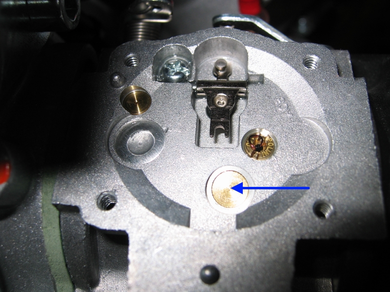
10. Main nozzle check valve It is extremely rare to have a defective main nozzle check valve #15 (WG) or #14 (WB) but it should always be checked to see if it is stuck or gummed up when doing a carburetor rebuild. If it is gummed up, the engine will not idle properly because air will flow from the main nozzle back into the metering chamber. This will stop or reduce fuel from entering the idle circuit, depending on how badly the check valve leaks. It is easy to check whether the valve is leaking. Take a piece of thin tubing about a foot long and place one end of it tightly over the main jet (see arrow in figure below). Note the number of turns on the idle mixture screw and then screw it all the way in. If this is not done air will leak through the idle circuit and you will not be able to adequately determine if the nozzle is working correctly. You should be able to blow but not suck through the valve. When the check valve closes it will make a noticeable "click" if it is working properly. When finished with this test, restore the idle mixture screw to its original setting.
Note: In the WG, the high speed circuit also feeds the low speed circuit through the low speed jet. This is why the idle mixture screw must be screwed all the way in in order to test the check valve in the nozzle jet
If the check valve leaks, try spraying carburetor cleaner into the main jet so that it comes out the check valve in the throat of the carburetor. Let things soak for a few minutes then blow air (<25 psi) through the main jet. If it still leaks, you will have to replace the carburetor because the valve is not available as a separate item (in North America and the EU).
Furthermore, carburetor rebuild kits do NOT contain the special brass plug (see figure below of the WG, WB similar with a screwdriver slot) that covers the nozzle check valve well.
11. Install the idle needle #39 (WG) or #40 (WB) to 1 1/4 turns out from all the way screwed in or what the engine manual specifies. At high altitudes set it to 1 turn. Be very careful not to force the needle against the seat or it will ruin the carburetor. These are basic settings and will have to be tweaked later.
12. Install the new fuel inlet screen Using the eraser end of an ordinary pencil, gently push the screen all the way in so that it completely contacts the casting wall below the inlet hole on the side. If it is not pushed all the way in, fuel flow will be blocked.
13. Install the new inlet valve needle assembly i.e. the spring, the metering lever (ML), pin, etc.
14. Metering lever adjustment
(You may skip the following discussion here concerning the WG diaphragm types and go directly to the adjustment section, if desired.)
Walbro cannot help us with any kind of support or information on these
carburetors because they are not only obsolete (because of EPA rules) but are being used in an *unsupported* and *illegal* application according to Walbro i.e. aviation. Many of the
Walbro parts we use here have to be imported because of this, thanks to U.S. tort law.
Richard Cobb was the first person who noted the different types of ML diaphragms
in the WG carburetor: the button and the tang-type. He is the one who
gave us this important fact that helped unsnarl the ML height adjustment mystery. It depends on the origin of the diaphragms – whether they come from Asia/EU (left
figure) or from the U.S. (right figure). The U.S. diaphragm has a button while the Asia/EU diaphragm has a tang.
However, in recent years both types of diaphragms have turned up in all regions. Note in figure #1 below that the tang-type has a greater height (1mm) than the button-type above the body of the diaphragm.
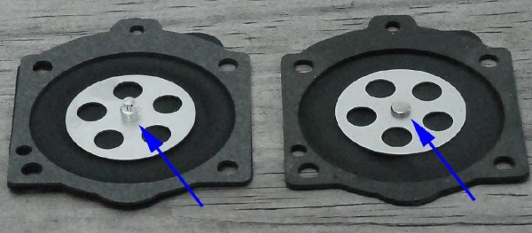
figure #1 – photos courtesy of Richard Cobb
This is why the ML height must be adjusted differently for each type of diaphragm.
The obsolete Walbro documentation does not note these differences.
figure #2 (below) is a close-up of figure #3 of the metering lever with a depth gauge set to the correct value (with the digital caliper) and is in place. The black double arrow is the actual height of the metering lever but it is impossible to measure this dimension. Instead, we measure the distance from the ML diaphragm gasket flange surface (see figure #3) to the top of the metering lever (the blue arrow in the figure). The upper red arrow points to the straight edge of the depth gauge which rests on the diaphragm gasket flange surface. The bottom red arrow points to the extended tip of the depth gauge which just "kisses" the top (and end) of the ML.
The distance between the (2) red arrows in figure #2 is what we set when we adjust the metering lever height. It is a critical adjustment which must be set exactly. Having the distance too great can result in the engine leaning out (and burning up).
When this distance is too great, the diaphragm will be unable to fully open the fuel inlet valve (on the other end of the ML) and the engine can be starved for fuel, especially at or near full throttle operation, if the ambient temperature is very cold, and/or if the fuel pump is weak (e.g. needs a rebuild). If the distance is too little, the button/tang on the diaphragm will rest against the ML at idle and the ML valve will leak fuel making it hard to start, impossible to adjust the idle, and possibly flooding the engine. You can immediately and easily test for a leaking ML valve by using a pop-off gauge.
Walbro's Service Manual correctly notes that ML height affects the fuel/air ratio entering the engine but the manual fails to note that this is true ONLY for gross maladjustments of the ML lever height i.e. 1.0mm or more off either way. The only important consideration is that the ML diaphragm is able to fully open and close the ML inlet valve.
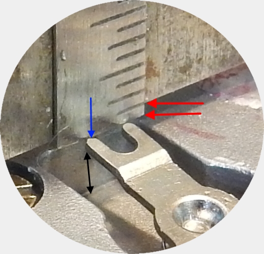
figure #2 (above)
The red arrow in the figure below points to the close-up detail given in figure #2 above. The black arrow points to the face of diaphragm gasket flange. Note: You should never clamp a carburetor directly in a vise. Use wood blocks on either side to protect the faces of the carburetor.
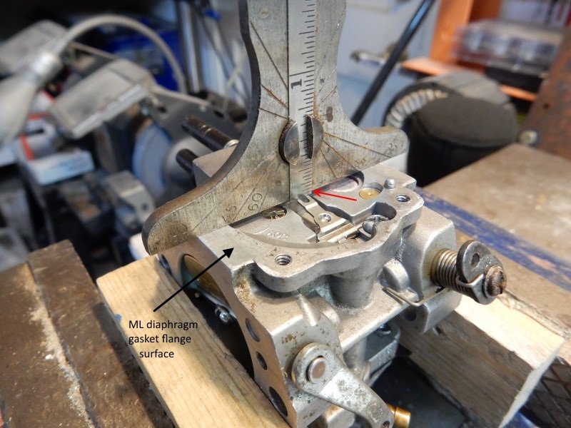
figure #3 (above)
Do not use the official Walbro depth gauge (or a clone) for the WG carburetor that is pictured here!
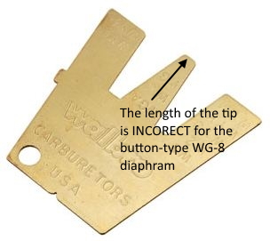
The official Walbro depth gauge and all of the clone gauges can only be used to adjust the ML value of the tang-type diaphragm and not the button-type diaphragm which is usually found on the WG in North America and the E.U. The tang-type is about 1mm higher than the button-type.
Adjust the metering lever height
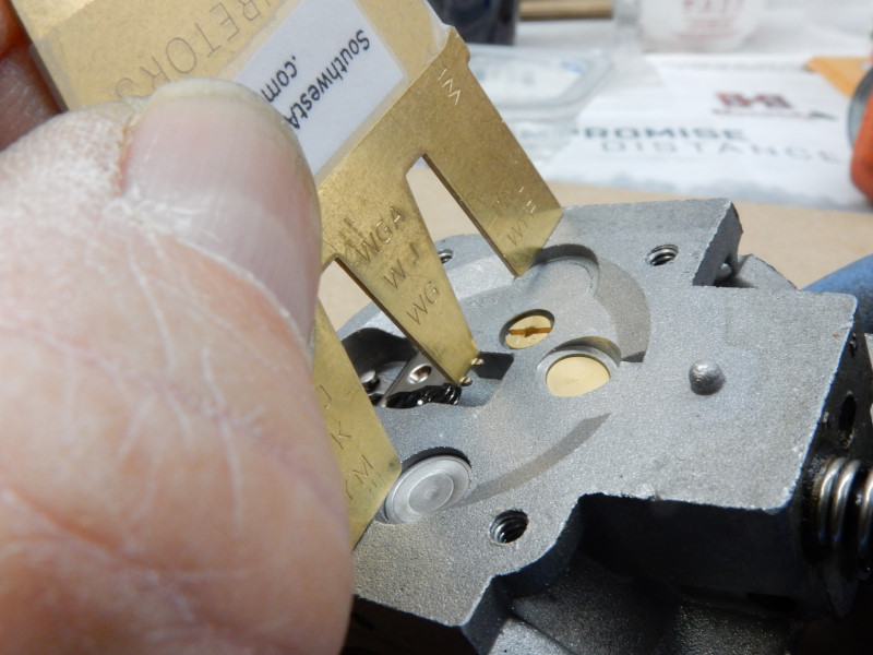
Southwest Airports (SWA) makes a custom gauge that is similar to the official Walbro gauge but has the correct dimensions for the *button-type* diaphragm found in most WG repair kits sold in NA and the EU. The SWA gauge is clearly stamped on one side with "SouthwestAirsports.com" so as not to be confused with the official Walbro gauge. Use of the custom gauge will save time, trouble, and expense for all pilots who service the Walbro WG or WB carburetor. Fortunately, the WB repair kits come with the height of the ML set correctly but, even so, the ML height should always be checked. This is because the ML lever can be accidentally bent in handling.
- Use the custom Southwest Airsports metering lever gauge to check the ML height of the button-type WG diaphragm ONLY. The gauge also has a tab (visible in the upper right of the gauge) for measuring the ML height of the
WB. If it is the correct value, go to step "c" below, if not, go to step "b". The tip of the gauge just kisses the end of the metering lever *without* opening the valve.
Here is a short video of how to use the gauge. The Walbro video
has more detail, if needed, on how to use a gauge of this type (the relevant section is about 9 minutes in). The ML height can vary ±
0.2mm.
This is what you will find when you measure the stock ML height with our custom made gauge. It is about 1mm too great.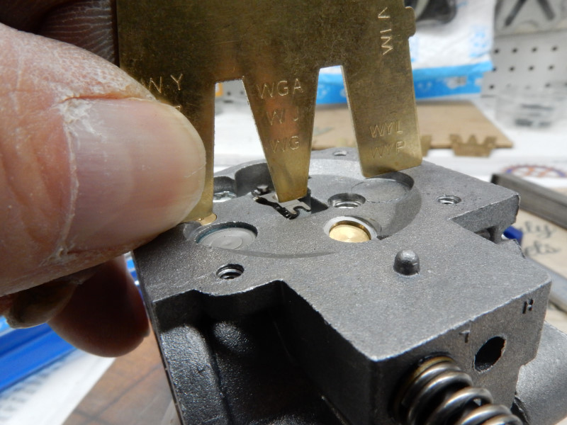
If you do not have the SWA gauge or have a tang-type diaphragm, follow these steps:
Use a digital caliper and depth gauge to set the correct value
WG: button-type = 0.7mm or tang-type = 1.7mm
WB: 1.19mm-1.59mm. The WB rebuild kit has the ML lever set to the correct value by the factory so it does not need to be adjusted. However, it is a good idea to check the ML height anyway in case the ML may have been bent during shipping and handling.
Use of the special base with a digital caliper is faster, more accurate, and saves a step than using an ordinary depth gauge. The gradations on most depth gauges are not fine enough to give an accurate measurement which is why we need the digital caliper.
If you do not have the special base, use the caliper to adjust the depth gauge so that the tip of the gauge rule protrudes the correct amount. For more detailed information on the difference between the tang and button-type diaphragms, you can take a look at this page. - Adjust the ML height, if necessary There are two ways to do it. The second way is much easier to do.
1.) Remove the ML lever. Hold the side going to the valve (the short side) with a pair of needle-nose pliers. Bend the long side up or down a bit depending on whether the ML value it too great or too little, respectively. Be careful doing this as you must not deform the pivot hole going through the center of the ML.
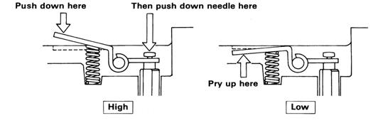
2.) Alternately, use your fingers to adjust the ML. The ML does not have to be removed. It is highly recommended that pilots watch the Walbro video on how to do it (go about 9+ minutes in). They recommend using screwdrivers but a fingernail works just as well. Be very careful if you use a screwdriver. The image below is from the ZAMA service manual.
- Double check your work. Connect a pop-off gauge to the carburetor, pressurize the system to just below the pop-off pressure value
e.g. 15 psi. The pressure should hold or very slowly drop. Press down on the diaphragm side of the ML (the longer lever that has the spring below it).
The pressure should drop to zero *immediately*.
It is always better to error on adjusting the height *less* than more. If the ML value is way less (>0.2mm less than the specified value) the ML valve is forced open at rest and the engine will flood and not idle correctly.
Below, a properly adjusted ML
For the WB, install the circuit plate with the diaphragm and gasket.
15. Install the fuel pump and ML diaphragms, gaskets, and cover plates.
THE (2) DIAPHRAGMS AND (2) GASKETS ARE INSTALLED IN A DIFFERENT ORDER ON THEIR RESPECTIVE
SIDES.
The fuel pump diaphragm goes on first and then the gasket. The ML gasket goes on first and then the diaphragm. (It is the opposite of the
fuel pump side). Most
kits contain an ethanol resistant fuel pump diaphragm. If ethanol
blends are used, the special pump diaphragm (clear in color) can be used.
The downside of this diaphragm is that it is not as supple as the nitrile rubber diaphragm and will
not pump quite as well, especially in cold environments.
Tighten screws incrementally in a "X" pattern. If the screws are not tightened properly the carburetor will not work.
IF YOU HAVE A WG WITH A TANG-TYPE DIAPHRAGM (RARE THESE DAYS), BE CERTAIN THAT THE SLOT IN THE ML IS ENGAGED WITH THE TANG OF THE DIAPHRAGM. If it is not engaged, the ML lever valve will NOT function correctly.
16. Check the pop-off and rest pressures Go to the link and follow the steps. If you do not have a pop-off gauge, this step can be skipped but you will not be sure of what is wrong if you have problems with the carburetor later on. If you do not have a pop-off gauge you can check whether the ML valve is leaking by connecting a piece of tubing the fuel inlet fitting and attempting to blow through the tube. It should be impossible to blow any air into the carburetor. While keeping air pressure in the tube, push down on the priming lever. It should be easy to blow air into the carburetor.
17. Engines with internal pulse ports The carburetor to reed valve body gasket MUST be installed properly for the pump to work optimally.
18. Install the carburetor on the engine, install the air box (if there is one), replace the fuel filter, but do not connect the fuel line to the carburetor. Place the end of the fuel line in a jar for testing in the next step. Note: Do NOT over-tighten the nuts which hold the carburetor on the engine. They should be just tight enough to squeeze the rubber air box gasket and make a seal. If you have a quality torque wrench, the proper value is about 0.9 Nm (8 in-lb.). Over-tightening will deform and ruin the gaskets.
19. Purge/check the fuel system Place a small amount of fuel in the tank and pressurize the tank via the priming tube (or squeeze the priming bulb, if present). Fuel should dribble freely out of the line that connects to the carburetor inlet fitting. This is an important step that ensures that the fuel system up to the carburetor is working properly and debris in the system has been flushed out. If ethanol fuels have been used, it is common for the filter on the end of the pick-up tube in the tank to become clogged with gel/goo. If this is the case, it must be replaced or have a hole drilled in it so it will never clog again. This filter is an obsolete holdover from when leaded motor fuel was used decades ago.
20. Pressurize the tank Connect the fuel line to the carburetor and pressurize the tank (or use the priming bulb). No fuel should leak out of the carburetor, including past the inlet needle valve. THIS IS A CRITICAL TEST AND MUST BE PERFORMED.
21. Prime the carburetor and start the engine using this method. If done properly, the choke will rarely be needed except to stop the engine in case of a kill switch failure or to start the engine in the air after a long period. If the carburetor does not have a priming lever, use the end of a cotton swab that has had the cotton cut off or a tooth pick. It is advisable to purchase a priming lever (or "primer spring") if it is missing. These are available from Miniplane-USA. Note that this technique for easily starting the engine will not work as well on engines where the pilot cannot easily position the inlet side of the carburetor lower than the outlet side e.g. the Minari and other engines with a vertically mounted carburetor.
22. Pump check valve and fuel line leak test We must be certain that the pump check valves are working properly *and* that there are no leaks at the carburetor fuel inlet. Once the carburetor is primed, look carefully at the junction between the fuel line and carburetor inlet fitting. Fuel must NOT drain back into the fuel tank. If you see this happening over a period of 5 minutes or less, it is likely that the fuel line connection at the carburetor inlet is leaking air. If the carburetor has been newly rebuilt, it is unlikely that the pump check valves or the metering lever valve is leaking. If there is no clamp on the fuel line at the inlet, use a 2.5mm (3/32") nylon zip tie double wrapped around the tubing to see if this fixes the problem. If this does not stop the leak, the rebuild that was done of the pump side of the carburetor is bad or the metal surfaces of the pump housing cover were not properly cleaned or are damaged.
23. Adjust carburetor After the engine has warmed up to operating temperature (70C), adjust the carburetor. Remember that changes in altitude, ambient temperature, fuel and oil type, and/or humidity will affect the low and high speed adjustments of a carburetor. Installing an EFI system is not a good idea for 2 stroke engines.
24. Test fly the engine. Properly tuned engines should be able to run at full throttle for at least 3 minutes. If you have rebuilt the carburetor properly and the fuel systems is 100% in order go to our troubleshooting page for answers.
![]()

