


Checking the timing on paramotors
by Had Robinson
updated December 23, 2021
Some newer paramotor models have a fixed ignition timing which cannot be changed (e.g. Vittorazi, newer Minari models, and Polini) so checking the timing is unnecessary. On the other hand, older models of the Vittorazi and Minari and all Top 80 engines have must have the timing set if the flywheel is ever removed.
In any case, checking the timing is not required unless the flywheel has been removed. If pilots purchase a used engine which has adjustable timing, there is no way of knowing if it has been changed. If you are having engine performance issues, it is a good idea to check the timing but be sure to first check everything else, especially the fuel and ignition systems, before wasting time checking the timing. If someone may have moved the flywheel or coil or if the engine backfires or runs particularly hot, running a timing check is a good idea.
There are three methods which may be used to check the timing.
Method A is the fastest of the three methods but requires the engine to be running with the flywheel and coil visible. A timing mark must be present on the flywheel for this test and the flywheel must never have been moved from its position set at the factory. If the flywheel has been moved (clocked) after leaving the factory this method will give a false value of the actual timing. Whatever the timing value that was last set will now be apparent, whatever it is.
Method B is quick but requires a top dead center gauge. The timing marks and coil must be visible. Some engines and models (e.g. the older Minari's) require some disassembly so that the front of the flywheel and coil are exposed. This method can be used with the motor on the frame but is easier if it is on a test stand. The actual timing value of the engine will be measured.
Minari only You may use the factory method (where the instructions read "magneto", read "magnet"). The factory method is easy to do.
Method C is precise to 1/2 of a degree or less and does not depend on any marks on the flywheel. These marks can get rubbed away, ground down by faulty coil spacing, debris, there may be multiple marks on the flywheel, or the timing was set by someone other than when the technician set it at the factory. It is the most accurate way to check the timing of the engine but the most time consuming. It also requires the most tools.
Method A
Special Tools Required
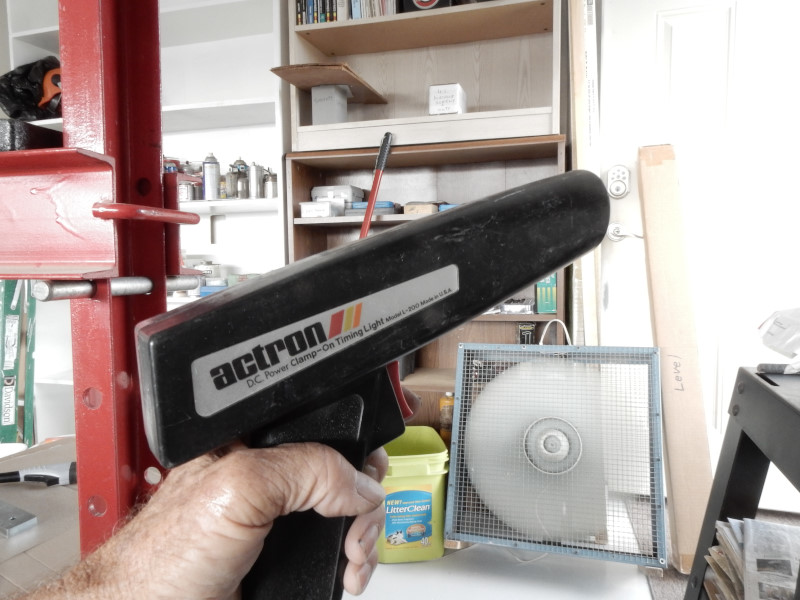
- Ordinary automobile timing light (available from Harbor Freight)
Steps
1. It is best to have the engine on a test stand where the bottom of the flywheel is conveniently viewable. If the engine is on the frame secure the prop and remove the gas tank if it is below the engine. Some method will be required to allow a connection to the tank so the engine can run such as placing the fuel tank to the side of the frame or adding some extra tubing, as needed.
2. Connect the timing light to the secondary wire and a power source per the instructions that came with the light.
3. Use some white-out to highlight the timing mark on the flywheel. The view here is the left side of the engine when facing the front. The timing mark is about 12mm 1/2" from the trailing magnet on the flywheel.
4. Start the engine.
5. Orient the timing light so it points up from below the engine to the trailing edge of the coil.
Here is a video of the timing light in action. It is a little hard to see but the highlighted timing mark is exactly at the trailing edge of the coil, a value of 14 degrees BTDC.
Method B
Special Tools Required
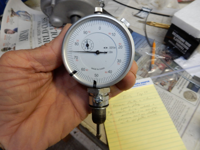
- Top dead center indicator – This can be made from a cheap dial indicator and an old spark plug with the insides removed. For details on how to make this tool or buy a commercial one, see the special tools required section of the timing page. The commercial indicator costs about 5X of what it costs to make one. At this time, there is no TDC indicator for engines with a 10mm spark plug.
Steps
1. If desired, remove the engine from the frame and mount it to a test frame. It is much easier to complete this routine if the bottom of the engine is easily visible.
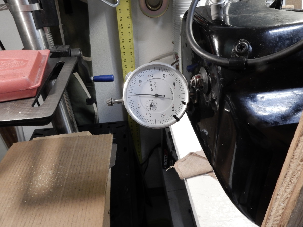
2. Install the top dead center indicator.
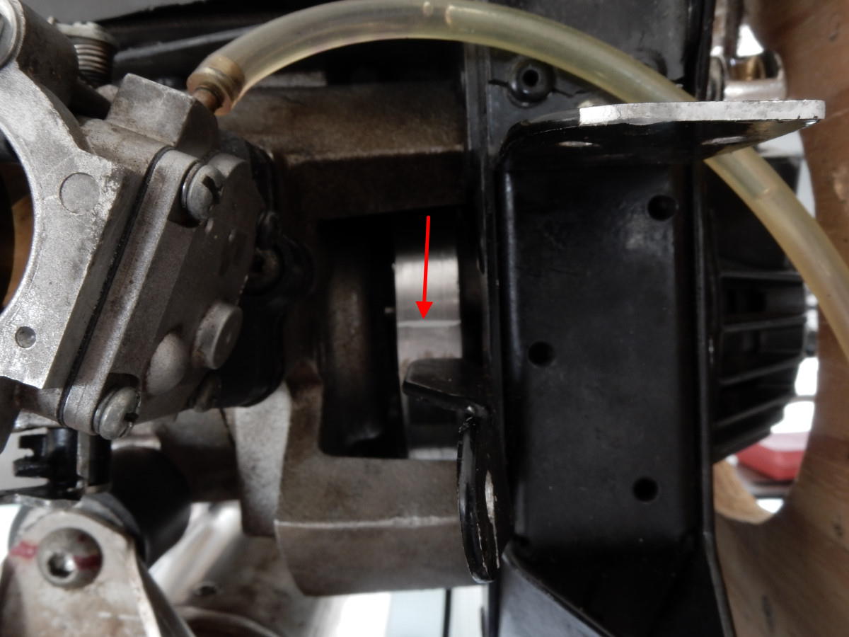
3. Orient the engine so that the trailing edge of the coil is visible (barely visible in the photo below).
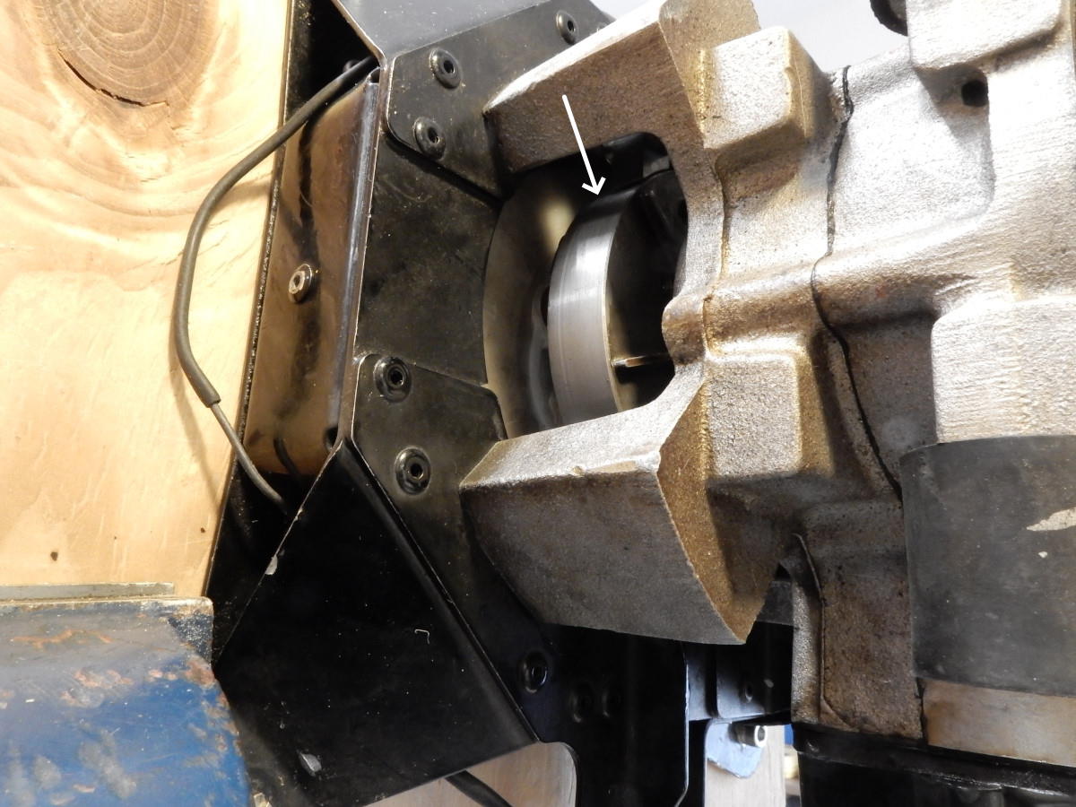
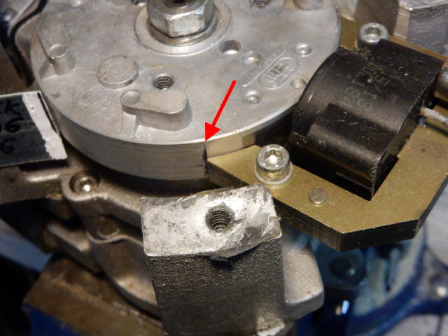
4. Remove the redrive or other parts that would prevent the use of a shim (black arrow in photo) to prevent the crankshaft from easily turning. In the Top 80 in the photo below the shim was placed between the clutch and engine frame. The shim must not be so tightly pressed in that it is impossible to turn the crankshaft by hand.
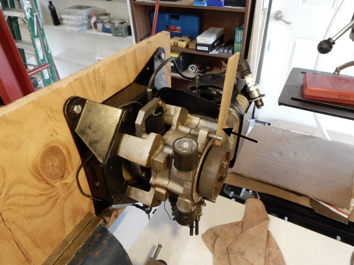
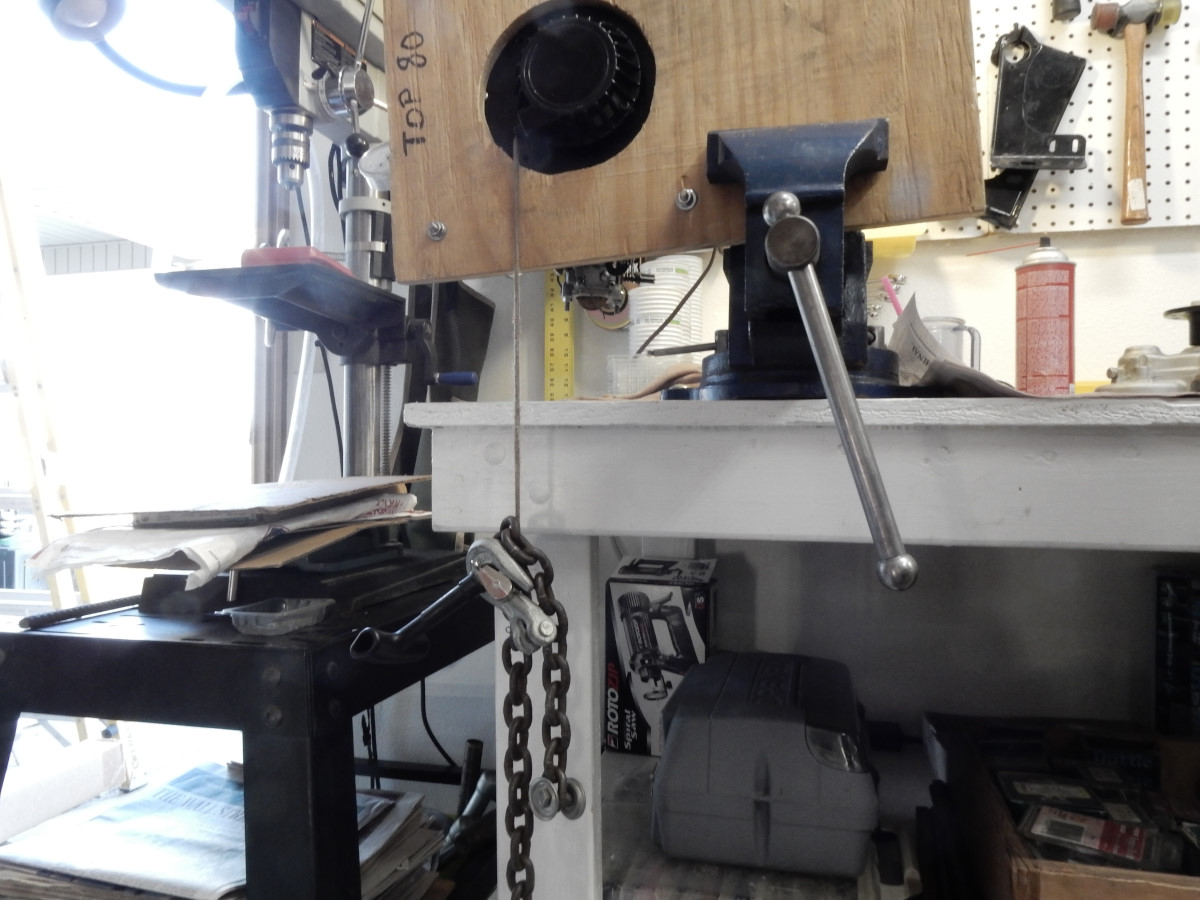
5. If the starter is present e.g. Top 80 figure out some way to extend the starter cord and weight it so the crankshaft can be rotated in either direction a turn or two.
6. Turn the crankshaft in the direction of normal rotation (clockwise when facing the front of the engine) until top dead center is indicated by the gauge. Set the gauge to "zero".
Minari engines only Once this step is complete, reference this page or use Method C on the check timing page in order to check the timing. Note: the timing of clutched and unclutched Minari engines are different. See the specs. Reassemble the engine and test run it.
7. Rotate the crankshaft in the *REVERSE* direction until the gauge reads the distance from top dead center (i.e. "zero") to when the spark should fire (i.e. the timing
mark on the flywheel). Many Italian paramotors use IDM ignition systems but the exact timing of the engine may vary. In the case of the Top 80, the distance is 0.90mm-0.95mm
(0.0354"-0.0374") or an advance of 14.5° BTDC. If your engine manufacturer does not supply the distance but does supply the degrees of advance, you will have to use Method A or C
unless you are particularly good with trigonometry and know how to convert the degrees of advance to distance on the flywheel. Paramotors that have the Selettra ignition system will
be happy to know that the timing is fixed so it is a waste of time to check it.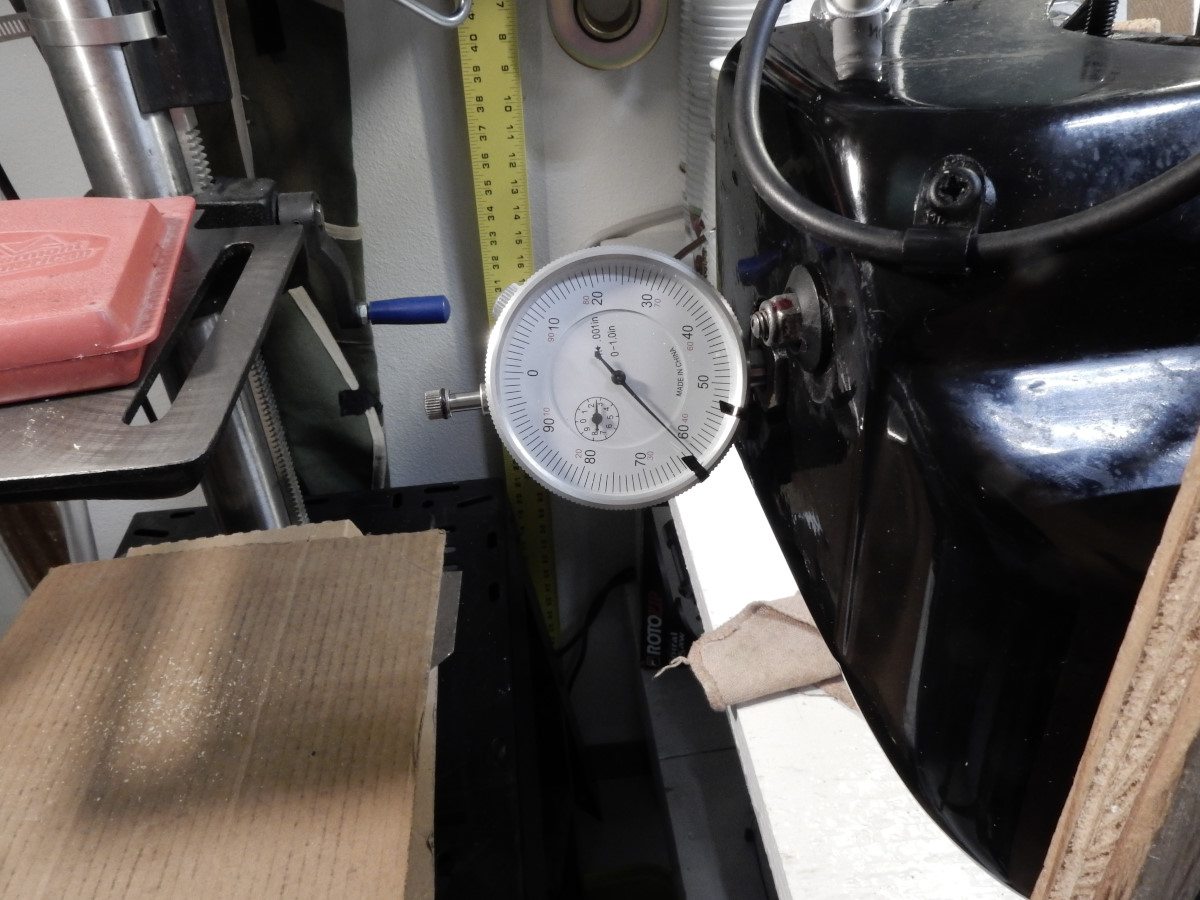
8. Flywheel mark Take a look at the location of the flywheel mark relative to the trailing edge of the coil. It should be right at the edge of the coil as in the photo below (front of engine removed for clarity). If the value is a thousandth (0.02mm) lower than specifications, all is good. If it is greater by the same it would be a good idea to retime the engine because the timing might be too advanced.
9. Reassemble the engine
Method C
This method is a very accurate way to set the timing without the need to reference a timing mark on the flywheel. The usual factory method for setting the timing must rely on a faint mark on the flywheel which may be missing.
Special Tools Required
Note: links to sources for these tools may change.
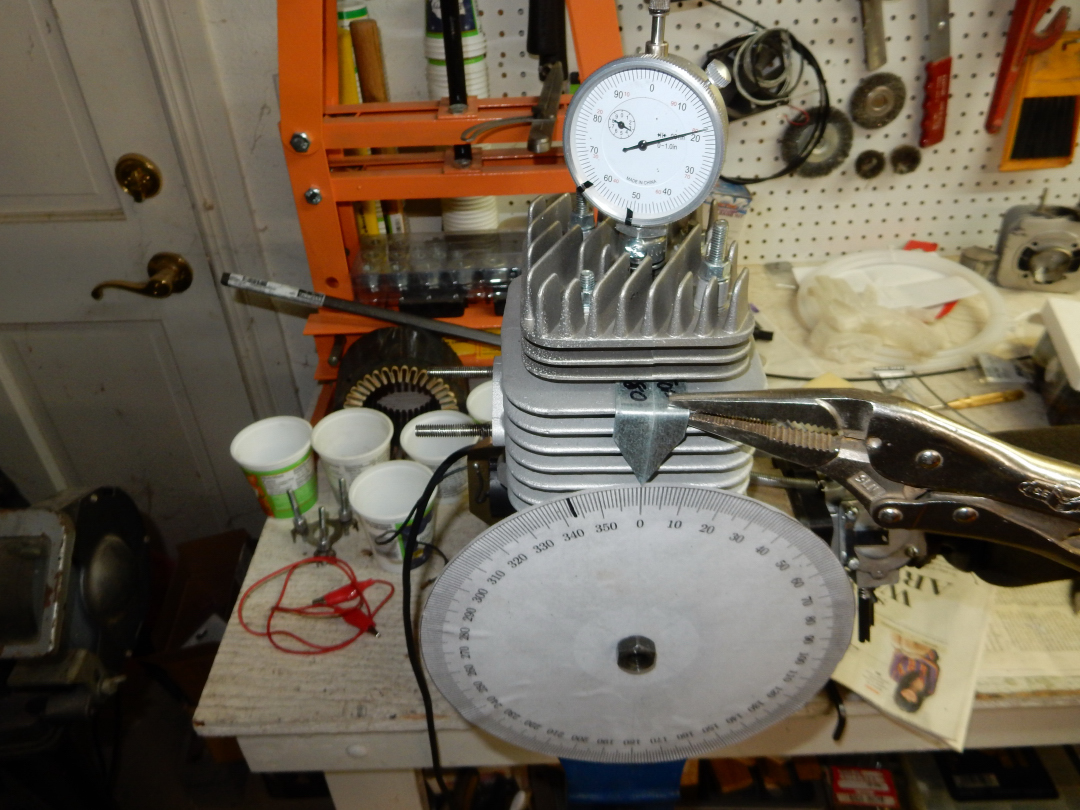
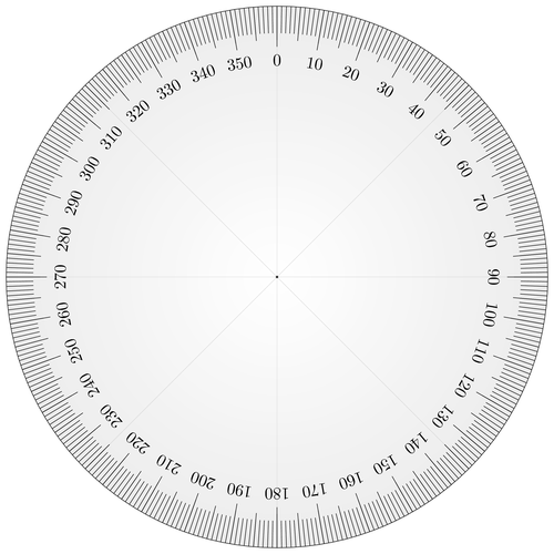
- Timing wheel – this can be made from a sheet of Plexiglas and this pattern or, better, purchase a valve timing wheel from a motorcycle tool supplier.
- Ignition Timing light and a 12VDC power source (storage battery or jump start system). This timing light is from Harbor Freight and has a built-in dial to set the advance so the light flashes at TDC. This extra feature helps set the timing to whatever value you need.
- Top dead center indicator – This can be made from a cheap dial indicator and an old spark plug with the insides removed. For details on how to make this tool or buy a commercial one, see the timing page. The commercial indicator costs about 5X of what it costs to make one.
- 24" test lead with clips at both ends
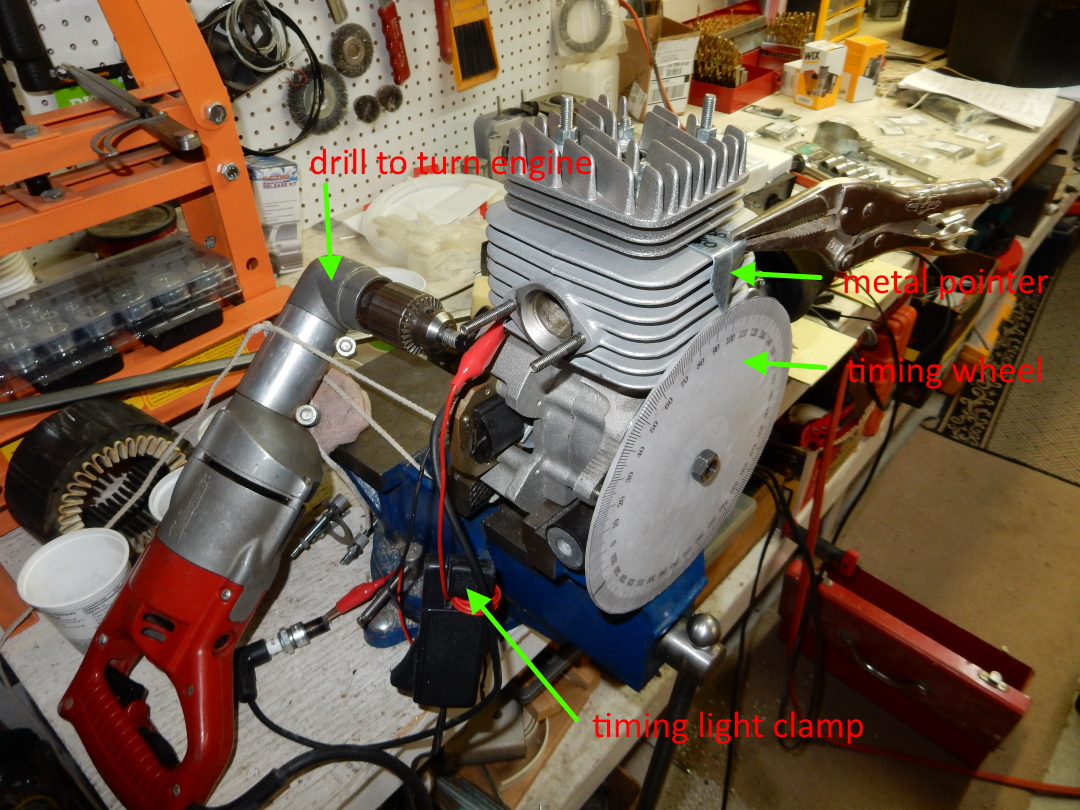
- Metal pointer that can be clamped to a cooling fin – It can be made out of a thin piece of sheet metal.
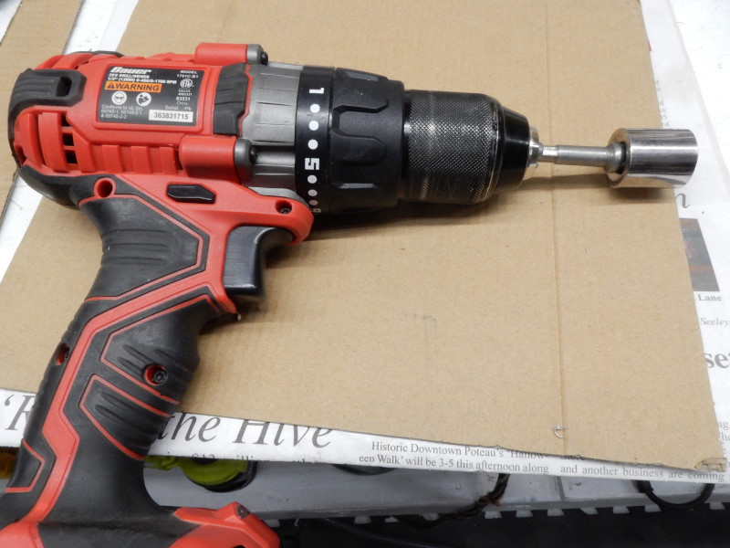
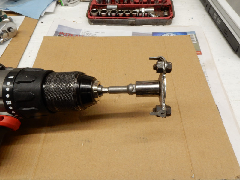
- A method for turning the crankshaft at 600 RPM. Any variable speed electric 3/8" drill will work. DO NOT USE A BATTERY OPERATED DRILL BECAUSE IT WILL SUDDENLY BRAKE THE CRANKSHAFT WHEN THE TRIGGER IS RELEASED, CAUSING THE TIMING WHEEL TO MOVE.
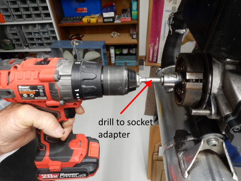
- A drill to socket adapter is needed for most paramotors.
- A new or used NON-RESISTOR spark plug
TOP 80 ONLY The Top 80 requires a jig unless the starter assembly is removed, a major task. It consists of a triangular piece of thin steel with a 1/4" bolt in the center attached to a modified Top 80 starter trident plate (part# M6S4 4a) works nicely. Using the jig does not require that the cooling box or any part of the starter assembly to be removed. This jig (in this position – with the trident tangs facing away from the flywheel) will fit nicely inside the starter pawls and contact them so the crankshaft can be rotated. A socket fitted over the nut and an adapter can be driven by an electric drill. Optional: Small pieces of windshield wiper hose can be put over the tangs to help protect the starter pawls.
Top of jig
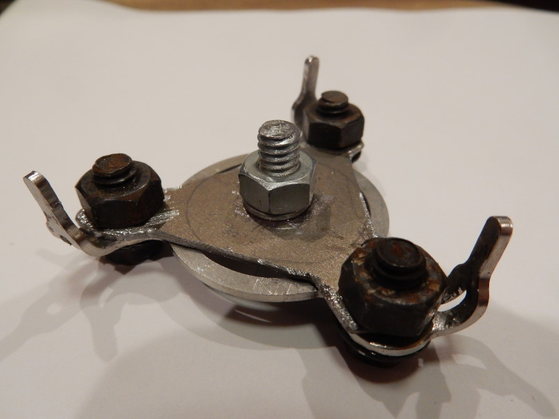
Bottom of jig
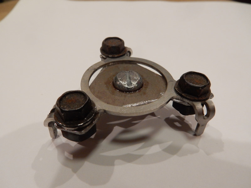
Alternately, a 1 1/2" cupped wire brush can also be squeezed in between the pawls and then turned with a drill. Whatever is used does not have to be elaborate. Anything that has a shaft and some way of contacting the starter pawls will work. It's worth the time to make the jig as it will save a lot of time later.
- A method to prevent the crankshaft from turning in order to loosen the pulley or redrive/clutch nut. If a 3/8" impact wrench
can be used, it is not necessary to hold the crankshaft. The redrive/clutch assembly nut must be removed in order to install a timing wheel.
Top 80 only A chain wrench, a
small oil filter wrench or a tie-down strap will work if the
clutch nut has not been over-tightened. If things are frozen, a
Vise-Grip chain-wrench
must be used to hold the clutch from turning while loosening the nut. Note: Chain wrenches that have teeth will ruin the clutch. If possible, apply copious amounts of
penetrating oil to the area
around the nut the night before. Prior to removing a frozen nut, apply (45) seconds of heat to it from a torch.
Minari and all others: Use an open end wrench on the flats of the drive pulley to hold it from moving or, in clutched engines, some way of holding the clutch. - Top 80 only Modified finger screws allow the easy removal and reinstallation of the starter, cooling box, and cooling fan assemblies if the jig above is not available.
Steps
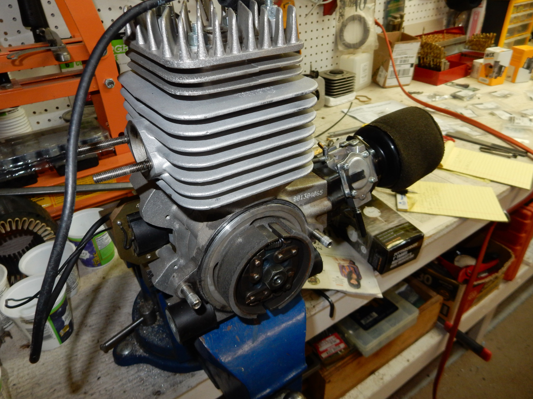
The photos below are of the Top 80 and Minari, other paramotors are similar.
1. Remove the engine from the frame and attach it to some immovable working surface. A steel plate or piece of plywood with holes the same size and spacing as the paramotor mounting bracket may be used. The plate or plywood, in turn, can be held in a bench vise or attached to some other structure.
2. Remove the starter assembly in order to expose the starter pawls (Top 80) or the flywheel nut (Minari and others). This must be done in order to have a method to rotate the crankshaft on the flywheel side.
Top 80 only: If the finger screws have been modified, then it is relatively easy to remove the pawls, the cooling fan, and the cooling box. If you have the OEM (unmodified) finger screws, they must be removed by filing off the top of the riveted end of the screw so that the pawls can be removed and a 10mm long socket used to remove the screws. Alternatively, you can use the jig above to turn the crankshaft which will save about a half hour or more of time.
All engines: to prevent mistakes, take a felt-tipped pen and draw an arrow on both sides of the cylinder indicating the correct rotation of the crankshaft. It is easy to get things backwards (.) when the engine is in pieces. Be sure to check the coil gap. If it is excessive, the timing at idle and ease of starting will be affected. If it is too little, the center post of the coil may contact the flywheel after the engine gets to running temperature and ruin the coil.
3. Remove the spark plug
4. Remove the redrive or whatever exposes the other end of the paramotor crankshaft.
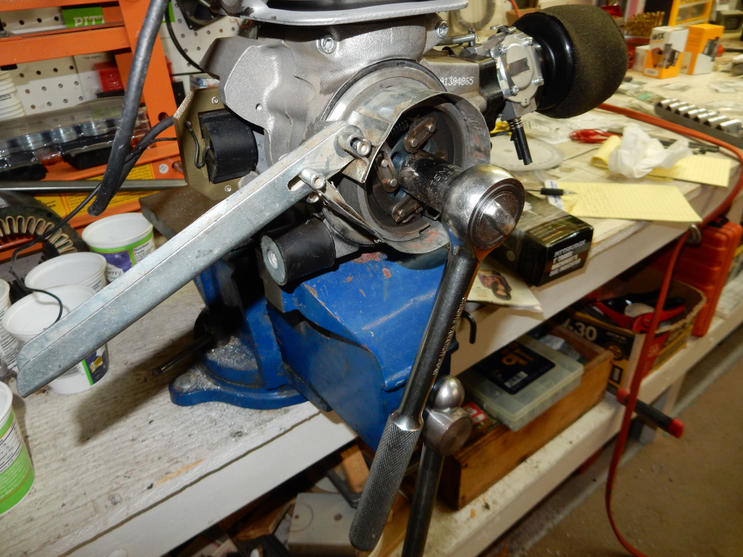
5. Clutch nut removal
Top 80 only Remove the nut on the clutch using an impact wrench or use the tool shown or a chain wrench to hold the clutch in order to use an ordinary ratchet to remove the nut. If these tools are not available, an ordinary ratcheting strap can be used to hold the clutch. Install the timing wheel and pointer on the clutch side. Tighten the nut by hand just enough to hold the timing wheel from turning.
Minari only Attach a deep 12mm x 1.25 nut (the nut in the Tusk crankshaft puller/install tool kit works great) to the end of the flywheel end of the crankshaft. (You will need to remove the starter.) Attach the timing wheel to this end of the crankshaft with a 12mm bolt, a washer, and another 12mm nut. The bolt/nut assembly should be just tight enough to keep the timing wheel from turning easily.
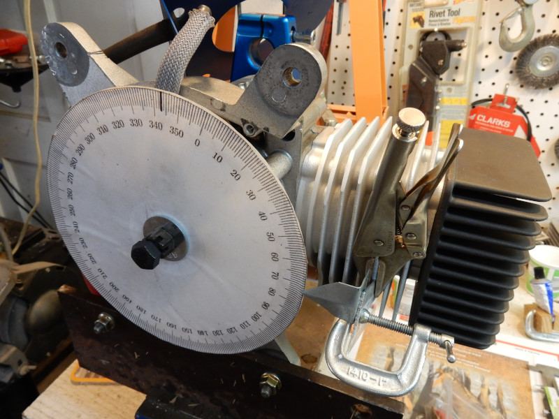
6. Install the TDC dial indicator Attach the pointer to one of the cooling fins on the engine. Tighten the clutch nut just enough so that the timing wheel will not rotate relative to the crankshaft. Use the TDC dial indicator to set the piston at TDC (its highest point), adjust the timing wheel to read "0". A mark may be put on the timing wheel at the correct timing value. If the value is 17° BTDC, place a mark on the timing wheel at 343° (360-17=343). The mark is for reference. When running the timing light it makes things much easier to see, even if the actual value is different.
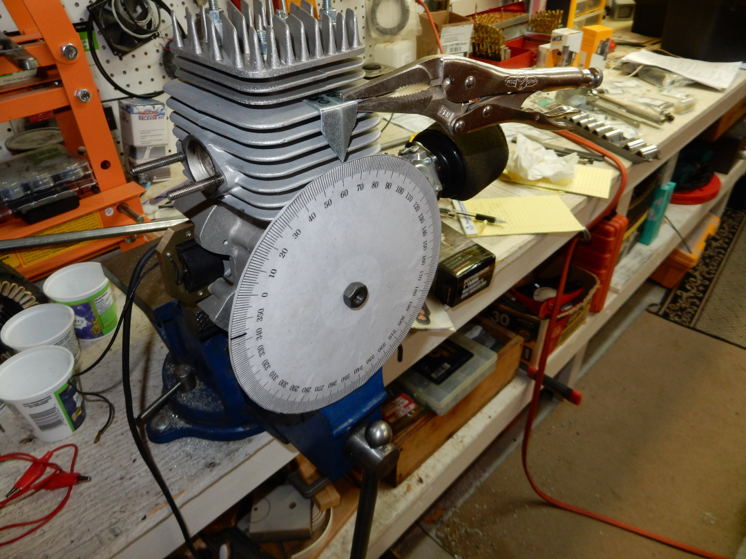
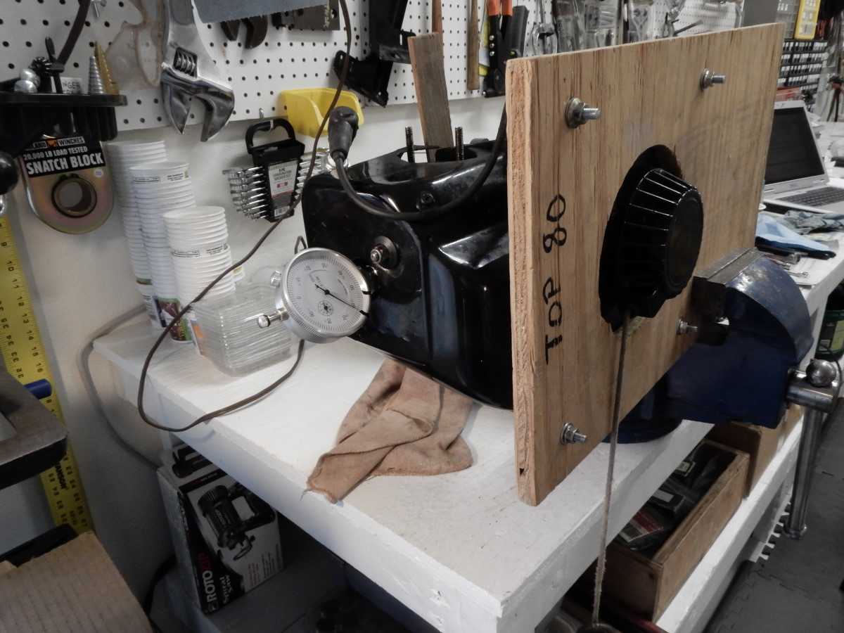
Details of the TDC dial indicator and special holder for attaching it to the cylinder head.
7. Remove the TDC dial indicator after setting the timing wheel to TDC. Double-check that the clutch nut is snug. If things get loose, the timing measurement will be incorrect. If the nut is over-tightened, it can crack the timing wheel. On the Minari and others, tightening the nut too much will bow the timing wheel so that it hits the pointer.
8. Attach the timing light to the 12V source. A jump-start battery works well for this light-duty electrical need. Open the jaws on the sensor cable of the timing light and wrap the test lead 4X or more around the jaws. You have to do this because most timing lights will not be sensitive enough to fire with the low energy, inexpensive ignition systems of most paramotors.
9. Connect the spark plug to the secondary wire on the engine. Connect one end of the test lead to the grounded tip of the spark plug and the other end to the engine (a cooling fin). DO NOT CRANK THE ENGINE UNLESS THE SECONDARY IS CONNECTED TO A GROUNDED SPARK PLUG. You must have a spark plug connected in series because the timing light will not work unless there is an actual spark at the spark plug. Do not let the steel case of the spark plug touch any part of the engine. It must be grounded through the test lead.
10. Rotate the crankshaft Be certain that you have removed the dial gauge before continuing. Attach the drill to the jig (Top 80) or the flywheel nut (all others). Turn the crankshaft in the correct direction 600 RPM from the flywheel side. Use an electric variable speed drill, NOT a battery operated drill (the photos below are for illustration only). Battery operated drills stop very suddenly when the trigger is released which will cause the timing wheel to move. Electric drills do not do this.
At 400 RPM the timing will be 2-3 degrees less (retarded) than at 600 RPM. It is important that the timing be checked at the maximum advanced value which is largely achieved at 600 or more RPM.
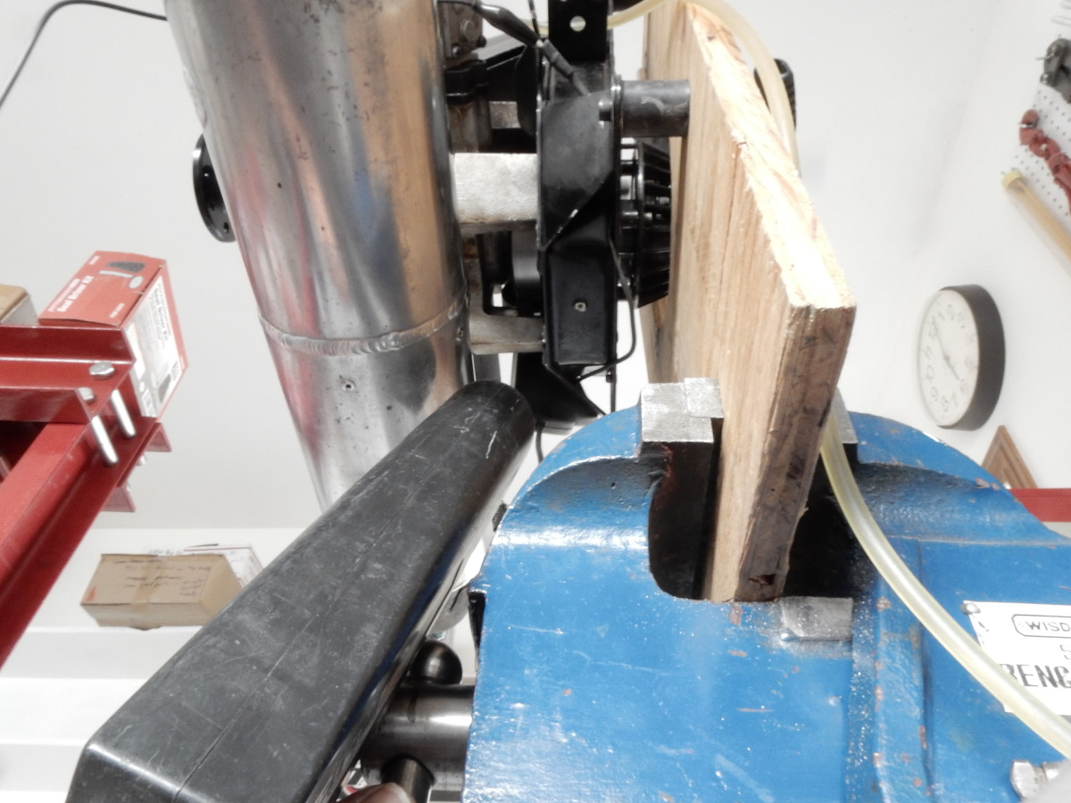
Setup to turn the crankshaft: an electric drill, drill to socket adapter, and the correct sized socket to fit the nut on the end of the crankshaft. A "wobble" 3/8" extension helps greatly in preventing stress on the drill. These photos are for illustration ONLY. Do NOT use a battery operated drill to turn the crankshaft!
Jig to turn the flywheel end of the Top 80 crankshaft. The jig is pushed down next to the starter pawls and catches them (the Top 80 starter must be removed in order to access the pawls). Put short pieces of rubber tubing on the modified pawls on the adapter.
As the RPM is increased from 200 RPM, the timing will advance by about 1.5 degrees when 600 RPM ±100 RPM is achieved on many engines You will know that you are about the right speed when the timing stops advancing.
Make a note of the timing value.
Top 80 ONLY: The factory method used to initially set the timing gives a mechanical advance of 14.5° BTDC +/- 0.5°. Pilots who have set the timing to 17° BTDC measured with a timing light have not reported any problems. Even with the timing set correctly, the actual timing will vary, depending on the rotation speed of the flywheel, the condition of the coil and what the coil gap is. Measured values between 14° and 17° degrees should not cause any issues. For every 1° of timing change, the piston moves 0.1mm (.004") and the flywheel 0.8mm (.032"). The timing specification has a tolerance of 0.05mm (.002") which is 1/2° +/- range in the timing or 14°-15° BTDC.
For other engines: Please check the respective timing specifications. IT IS ALWAYS SAFER TO BE A FEW DEGREES ON THE LOW SIDE OF THE TIMING THAN ON THE HIGH SIDE.
11. Recheck timing Remove the means by which the crankshaft is turned and re-install the TDC dial indicator. Carefully move the crankshaft to TDC. The timing wheel must show TDC (0°). If it does, the timing has been accurately measured. If not, this means that the timing wheel has moved and the process must be repeated starting at step #6.
12. Reassemble the engine by following steps #1-5 in reverse.
![]()

