


Secondary wire repair for any ignition coil
by Had Robinson
A. Discussion
To make a permanent repair (not replacement) of the secondary wire pilots can use this technique when: a.) the high tension coil terminal is not easily accessible, b.) the secondary wire is not 5mm in diameter, or c.) it is a different coil than the IDM and does not have the typical high tension terminal.
This repair has been thoroughly tested in wet, humid environments.
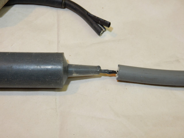
Small two cycle aviation engines all have a low flywheel mass to save weight. Consequently they all experience severe and damaging vibration. This leads to early failure of engine components, including the secondary ignition wire that goes from the coil to the spark plug. Unfortunately, the Miniplane OEM supplier (IDM) uses an inexpensive secondary wire that burns out quickly compared to automotive grade wire. The thickness of the automotive core is about twice that of the Top 80 OEM core. The core itself is made up of a carbon impregnated sheath surrounding hundreds of tiny flexible synthetic fibers that give it strength. In tests done here it is easy to tear/break the Top 80 carbon sheath with gentle flexing compared to the automotive grade sheath. Most automotive secondary wire does not use a carbon core but has a high resistance spirally wound wire core. This grade of wire, however, will eventually suffer a break in the core due to the intense vibrations of all 2 stroke paramotor engines. A much more expensive wire is available that will last much longer (see "Parts required" below).
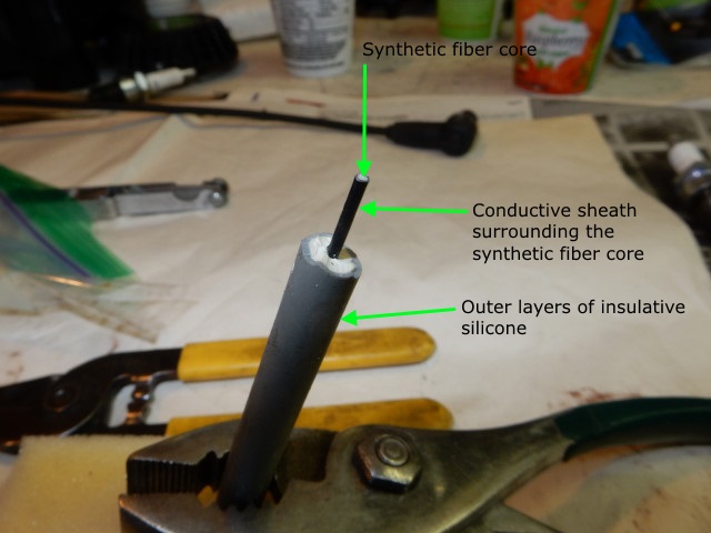
The structure of most modern secondary ignition wire.
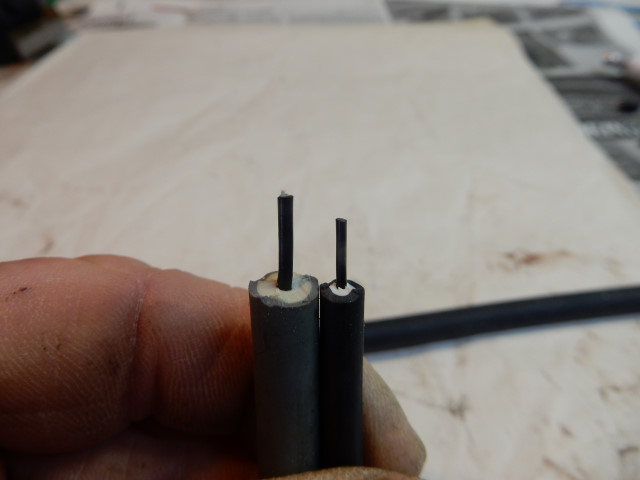
The automotive grade secondary wire compared to the OEM Top 80 wire.
If a temporary repair is needed, go to this page for instructions.
This repair should take less than 45 minutes to complete
B. Repairing the secondary wire
1. Before you begin, check the coil to be sure it is good. If you need help on how to use a digital multimeter, Fluke has instructions here on how to measure resistance. Stick a sharp needle into the existing secondary wire about 7.5cm (3") from the coil. It must go in far enough to contact the carbon core in the center. Check the resistance from the needle to the engine ground (one of the aluminum cooling fins on the cylinder). It should be about 10K Ohms which is the resistance of a good coil plus the resistance of 7.5cm (3") of secondary wire on a Top 80 and other engines which have a resistor-type secondary wire.
Engines without a resistor-type secondary wire will have a lower value. If you do not see any resistance at first, withdraw the needle and stick it in again 12mm (1/2") closer to the coil. If no resistance is found, move the needle closer to the coil and check. Continue moving the needle closer to the coil, as needed. There must be a point at which resistance can be measured. It may rarely be necessary to remove the existing secondary wire entirely in order to measure the coil secondary resistance (see below for how to do this). If it is less than 10% of 10K Ohms (or open/infinite) in the IDM coil, the entire coil assembly must be replaced.
2. Parts required
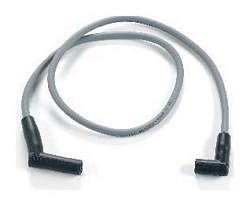
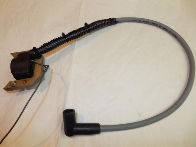
- Replacement secondary wire like the one shown below from a local auto parts store. The wire should be at least 24" long and have a permanently attached spark plug boot at the end. The other end has a fitting for the distributor cap. The caps are usually labeled. The cap for the plug is longer than the one for the distributor cap. The wire can be 7mm or 8mm (preferred) in diameter. The 8mm wire will last longer than the 7mm. If a premium wire is desired see if the parts store has a wire with a metal helix core. (These special wires may not be available, however.)
- 1/2" OD wire loom
- 1/4" nylon cable clamps – Ideal #772835L for 8mm wire only
- 1/2" & 3/32" heat shrink tubing (HST)
- 5 minute epoxy
- Spark Guard (dielectric paste)
- Nylon quick-ties, preferably those with a fastening hole – use only commercial electrician quality ties as the other kinds go bad quickly.
- ALNOX or an equivalent dielectric grease. This repair will not last if dielectric grease is not used.
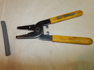
- A wire stripper used by electricians – it must be able to strip #10 wire at a minimum (see photo below).
The only special tool you will need is a hot-air gun to shrink the HST ($15 from Harbor Freight).
One end of the replacement wire fits over the spark plug and the other plugs into the distributor. We only need the end that goes on the spark plug (right side of photo). It is important that the spark plug end have a 90 degree connector, as shown here. The photo on the right is that of an electrician's wire stripper which must be used to strip high voltage secondary wires.
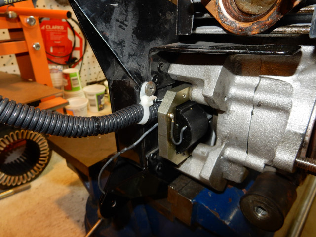
3. Top 80 ONLY Loosen the (4) screws which hold the cooling box to the engine using the extra long 5mm hex bit. Undo the screws about 5 turns. Pull the cooling box away from the coil terminal 5-6 mm (1/4") and leave it until you have completed the replacement. This will give you ample room to work on the coil. You can now easily use a Dremel-type tool or a round file to increase the clearance between the terminal and the cooling box as shown in the photo below.
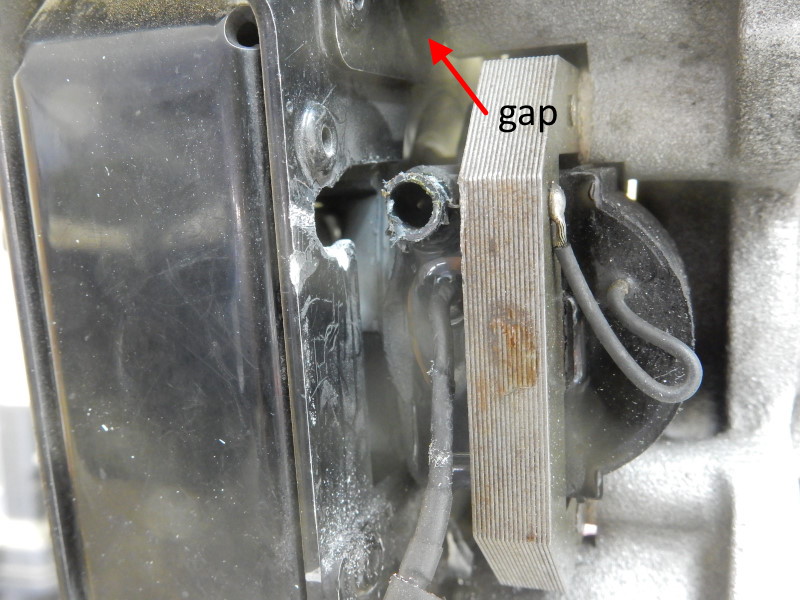
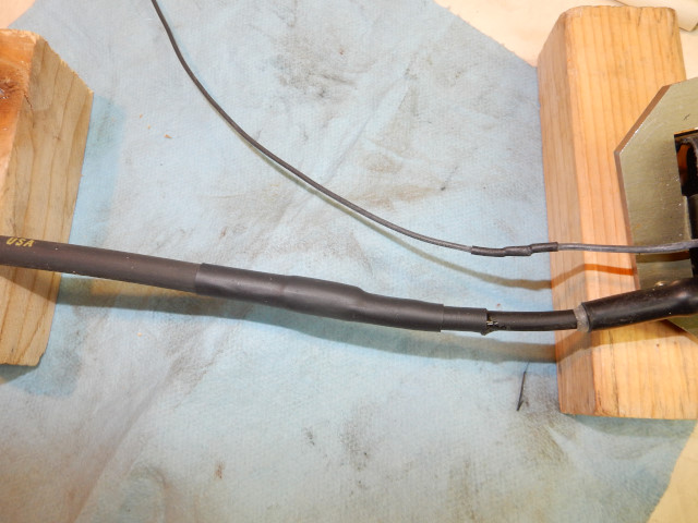
4. Cut the original secondary wire about 2" from the end of the heavy sleeve that protects the wire as it goes into the coil (see red arrow in the first photo below). If the secondary wire is good less than 2" from the end of the heavy sleeve, you may not have enough of a stub of the original wire to make this repair secure. Then you must replace the entire coil assembly.
In the second photo below, I removed the heavy sleeve in order to check the wire condition but this should not be necessary. At this point, check the secondary resistance of the coil again, just in case. It MUST be within specifications. For example, if the stub is 3" in length from the coil, the measurement should be around 10.2K Ohms (8.5 + .57 + .57 +.57). If the values are greater than 10% less, I would replace the coil because it likely has some internal shorts that will only get worse over time.

The coil here has been removed from the engine for clarity. Using pins, it is easy to see the internal structure of the OEM secondary wire. The OEM carbon polymer sheath is very fragile.
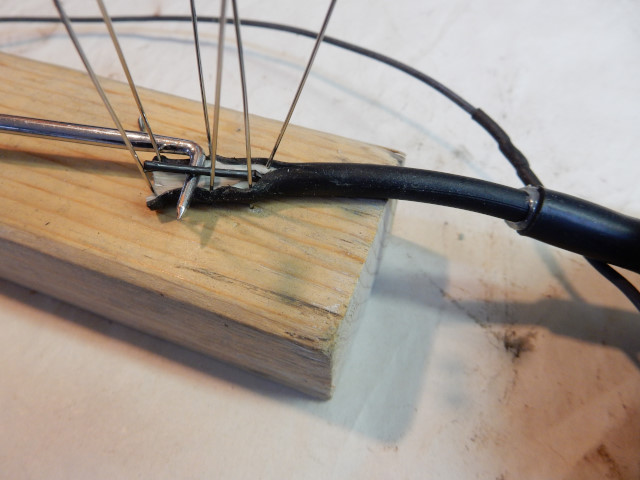
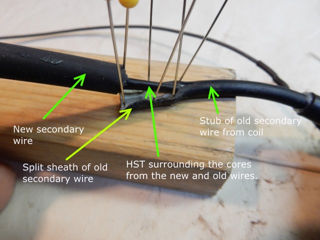
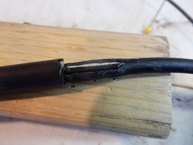
5. With a razor blade, make a slice lengthwise 1/4" from the end in the outer black/white insulation of the OEM secondary wire just deep enough to expose the inner core. Use a block of soft wood, some straight pins, and a pair of needle nose pliers to pin back the insulation, exposing the inner core in order to lift it out. Once the core is exposed, it is easier to slice open the insulation another 3/4" if it is pinned open without damaging the inner core. Otherwise, it will take a bit more time if you can't pin it open.
Remember that the carbon core is very fragile. Leaving the outer black/white insulation connected and intact allows it to make a "sandwich" (like a hotdog bun over a hotdog) around the new joint of the two cores, making it stronger and more durable. Mostly importantly, it protects the OEM core, as any slight bending of it will break it.
The HST needs to squeeze about an inch of the two cores together. In the photo below, the arrow points to the barely visible slice.
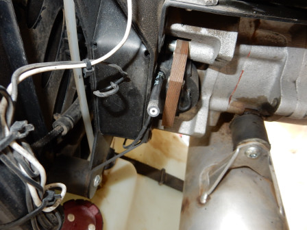
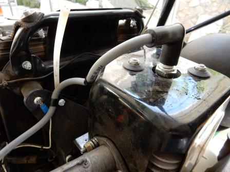
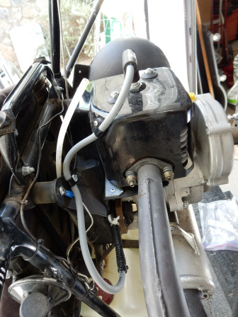
6a. Coil installed on the engine: Connect the spark plug boot end of the new wire to the spark plug, install the (2) clamps, and dress the wire down to the coil, as in the last photo. Keep the wire tight in order to keep it from shaking and fragmenting the core prematurely. There must be enough slack at the plug end so the cap can be easily removed from the spark plug. Cut the new wire to an adequate length to make the connection at the coil end.
6b. Coil not on the engine: Cut the new wire so its overall length is 19".
7. Note: You may want to do a "dry run" of the next steps. Do not apply ALNOX, the epoxy, nor cure the HST in order to be sure you have everything the right length and the (2) pieces of HST pushed up on the new wire. The purpose of the next steps is to be sure that the new wire is strongly attached and sealed to the old wire from the coil.
Slide two 3" pieces of 1/2" HST over the new wire. Push them far up the wire towards the spark plug boot so they are far out of the way and unaffected by the hot air gun used in the next step. These will be used to strengthen the joint of the old and new wires and keep the joint from bending too sharply. Do not apply heat to the pieces of HST at this time.
8. Carefully strip 1" off the end of the new wire using the #12 wire size on the wire stripper. The stripper will not quite reach the core and prevent the cutters from nicking it. You might want to practice stripping a piece of the wire that was cut off before trying it on the final product. Coat both cores with some ALNOX. The ALNOX must be used to keep the cores from arcing between each other. If you have a syringe with ALNOX in it, just push the core into the syringe to coat it.
If it is not used, the cores will burn each other up after 50 hours or so. Put an inch of 3/32" HST over the original core (1/16" HST will work but it is a bit tight). Push the new carbon core into the HST that is on the original wire as shown below. This way, an inch of the cores will be in contact with each other. The pins are there to help make the photo clearer.
The most important part of this fix is to be sure the cores are firmly squeezed together by the HST.
Shrink the HST that surrounds the cores. You will have to lift out the core going to the coil a bit in order to do this. Let things cool off. The HST tends to stick to the wire insulation so you may have to carefully use a razor blade to free it from the black/white insulation in the slit. Next, push the joined cores into the slit made earlier, like a hotdog into a bun. Use a cotton swab to clean up an excess ALNOX that oozed out of the HST joint.
The OEM wire is "sandwiched" (below) but the new one is not – which is not a problem because the new wire is much sturdier and better made than the OEM wire.
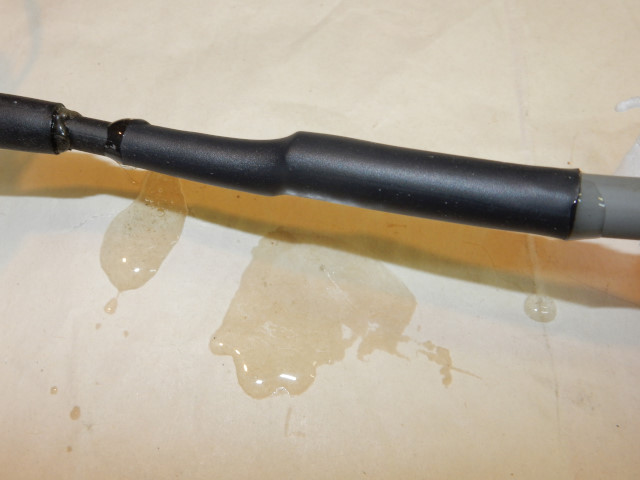
8. Epoxy prep: The epoxy tubes should be put in ice-water for (10) minutes in order to slow down the curing rate. Coat the exposed HST that covers the cores and the area of the joint 1/2" in each direction with 5 minute epoxy. You have to work quickly. Slide the first piece of HST that is over the new wire down so that it covers the new joint evenly. Shrink it with your heat source. The HST will squeeze the epoxy over everything and out the ends. It will FIRMLY hold the new and old pieces together and tightly seal everything from water, oil, and dirt. If the epoxy is omitted, the wires may eventually shake apart. Epoxy must not be used with the first piece of HST because it will come in contact with the carbon cores and may insulate them from each other, despite the ALNOX. When you are done, things should look like the photos below.
If done on the engine:
If done with the coil off the engine:
9. After things are cured and cooled down, slide the third piece of HST over the joint an inch closer to the coil than the other piece of HST. The two pieces of HST will be staggered and this greatly increase the strength of the joint. Shrink it.
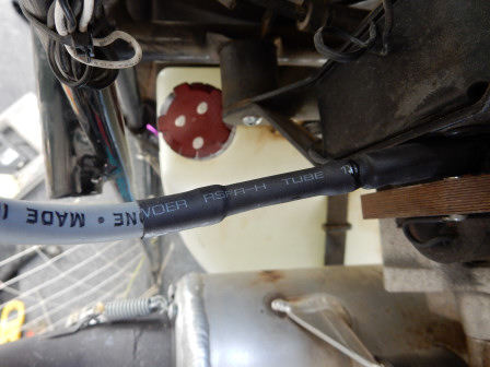
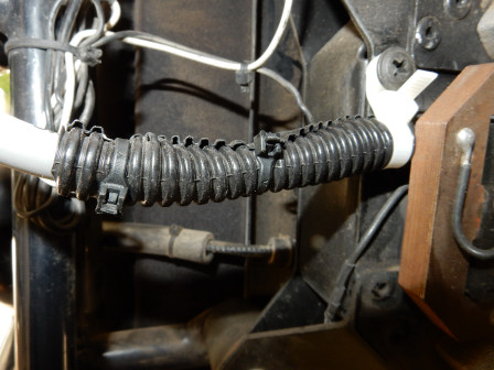
10. Cut a piece of wire loom long enough to go from the coil to at least an inch past the HST on the new wire. Butt the loom right up to the coil. It will help stabilize and strengthen everything and minimize shaking. Do not fill it with epoxy because you might have to remove the whole thing sometime in the future. Use small nylon zip ties to secure the loom on the new joint and wire. Use the nylon tie with the fastener hole to help secure things and make sure that things do not slide off. If this step is not done, engine vibration will eventually cause a break in the stub that comes out of the coil.
We are done.
Be sure to measure the secondary resistance again.
The clamps must be firmly fastened to the engine, just like the original. Failure to do this will ensure that the core will break and fail prematurely. It is best to use metal screws to fasten the clamps to the cooling shroud and engine frame rather than use the original plastic screw and a rivet. Note that the spark plug boot is bigger and more rugged than the OEM part.
If you make a mistake, remove the loom, slice off the HST with a razor, and start over. The engine below has already had another 50 hours of hard use with this repair and is working perfectly.
IMPORTANT NOTE: The boot is very tight on the plug. Use Spark Guard (dielectric paste) on the boot and plug to insure that the boot is seated completely down on the plug terminal. When installed the bottom edge of the boot will be about .2" (4.5mm) from the metal base of the spark plug. If the boot is NOT fully installed, the boot terminal will be damaged when the engine is running. Always be sure that the plug terminal has been installed with RED threadlock.
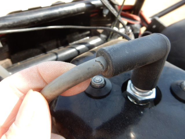
This modification greatly prolongs the maintenance schedule for the ignition system. However, even automotive grade wire can still wear out. After 150 hours, the severe vibration caused a crack in the insulation near the boot but it should last another 50 hours. If wire with a helix metal core is used, the repair should last the life of the engine.
![]()