

Cylinder head temperature gauge (including tachometer)
by Had Robinson
updated December 24, 2022
Discussion
A cylinder head temperature gauge (CHT) is an essential tool used to monitor the running temperature and health of any air-cooled engine. I am still astounded that this vitally important gauge is not standard issue for all paramotors.
It is also good to have an hour meter/tachometer so you will know if your engine is running at peak output and will know when maintenance is required. Would you own a car that did not have an odometer nor a temperature gauge/alert? You may never need them and could guess when maintenance is due, but then....
Why not have an exhaust temperature gauge (EGT), as do general aviation (GA) aircraft? The first reason is that it is rarely needed for a paramotor using a diaphragm carburetor (nearly all paramotors). The advantage of an EGT is that it detects changes in engine running temperature very quickly whereas a CHT can take 10 seconds to register a change. GA aircraft that are carbureted have the means to quickly change the air/fuel mixture during operation. For this reason, engine exhaust temperature has to be monitored closely or the pilot may burn up his engine. This is not so with a paramotor.
Secondly, an EGT costs much more than a CHT and is complicated to install on a paramotor. It requires drilling a hole in the exhaust manifold right at the cylinder head (which is not always possible on some engines). One of our engines at Southwest Airsports has an EGT but it has a float-type carburetor which is easy to adjust in the midrange, unlike diaphragm carburetors, because going lean in the midrange is very easy to do and could harm the engine. If pilots want to spend the money and time to install an EGT, do it but I do not think it is necessary.
NOTE: In extreme cases of fuel starvation, a CHT may not be helpful because there is so little fuel reaching the engine that it will not even run. In this situation, the engine does not overheat. Always do a thorough test of the fuel delivery system before assuming there are ignition or mechanical problems with the engine.
An unmodified Top 80, for example, will have a cruising temperature between 120°C - 170°C with the TTO CHT gauge, depending on ambient conditions and altitude. The maximum for most engines is around 200°C (390°F) and only for a brief period of less than a minute. Some of the bigger engines can safely run at 250°C (482°F). I have yet to see any Top 80 get even close to running the max temperature when correctly tuned. Having an engine run a bit cool (rich) will not do any harm. However, an engine running at less than 70°C will have problems with fuel vaporization which is necessary for efficient combustion. Another problem with a cooler than normal running engine is fouling of the piston rings and lands. This is especially an issue when using AVGAS.
Owner's manuals from smart Italian manufacturers always remind pilots to *NEVER* go to full throttle until the engine warms up (70°C or more). Vittorazi, for example, recommends that the 180 Moster reach 120°C before flight. This is because un-vaporized fuel in the form of droplets will not burn in the cylinder and just pass through. Less fuel, more air creates a lean condition and be severe enough to quickly overheat an engine. Additionally, paramotor engines are designed mechanically to run at a specified temperature which varies widely from manufacturer to manufacturer.
Pilots must know the maximum running temperature of their engine and not exceed it.
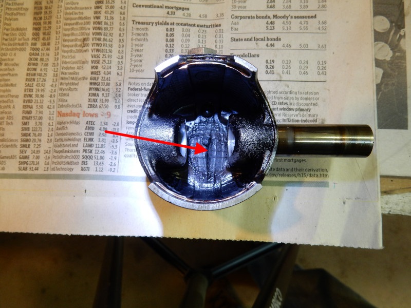
As the engine temperature increases to an excessive level, the piston will begin to expand because it does not cool as efficiently as the cylinder and head. As the temperature increases even more, the piston will expand enough that its diameter will begin to exceed the inside diameter of the cylinder. At this point, irreversible damage occurs to both the piston and the cylinder. If the temperature increases very quickly, the crown of the piston can melt at the center and form a hole. As things heat up even more, the piston will seize and the engine will stop.
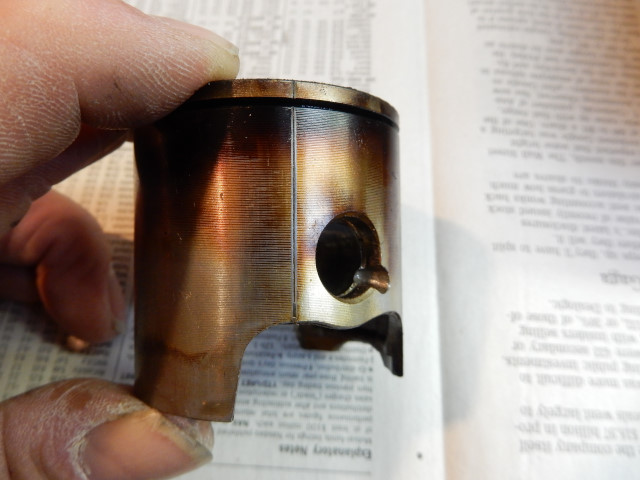
This is a piston from an overheated Top 80 engine. It had seized in the cylinder while running. Note that the lubricating oil on the surface of the piston has burned. Burnt oil cannot lubricate engine parts. If the pilot had had a CHT, an expensive repair could have been avoided. In this case, the overheating was caused by fuel starvation from a clogged fuel inlet filter and a worn out fuel pump. The oil used in this engine was probably some inexpensive brand because the oil burned so easily and why pilots should always use a premium 100% synthetic racing oil. Synthetic oils can survive at higher temperatures than all others but they also pollute more. Pilots who are concerned about this can buy synthetic oils that are not "racing" grade and they cost a lot more.
Running the engine too hot will destroy the lubricating properties of the oil. Burnt/charred oil can cause the piston ring to bind to the piston lands. In addition, the piston, ring, and cylinder will experience much greater wear.
Bottom line: a cool running engine will last longer and have fewer problems. While you are at it, you should also install a tachometer/hour meter gauge.
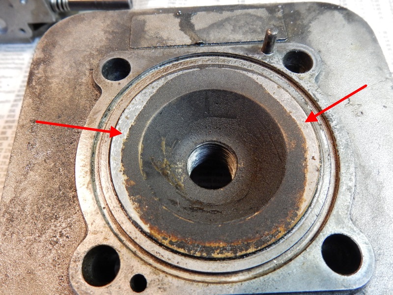
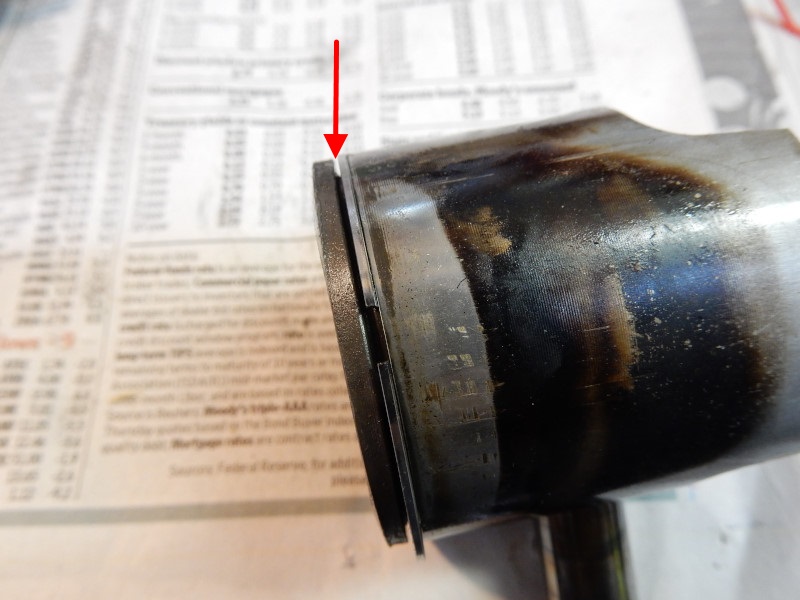
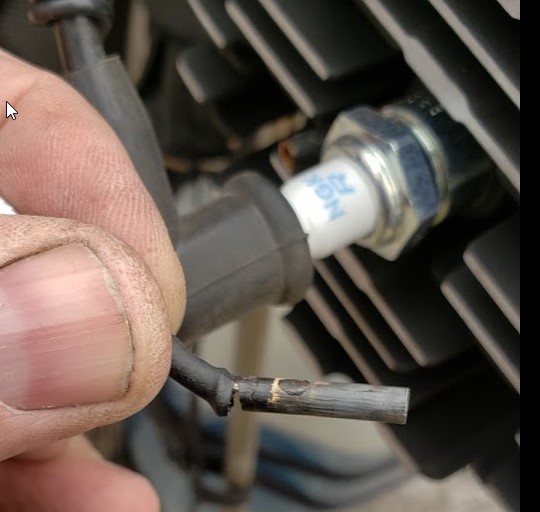
Here are some photos of what can happen to an engine. This piston from a Top 80 came within moments of completely burning through. The piston ring lands got so hot that they separated and melted causing the ring to become loose (3rd photo). The melting piston began to hit the cylinder head, as well (2nd photo).

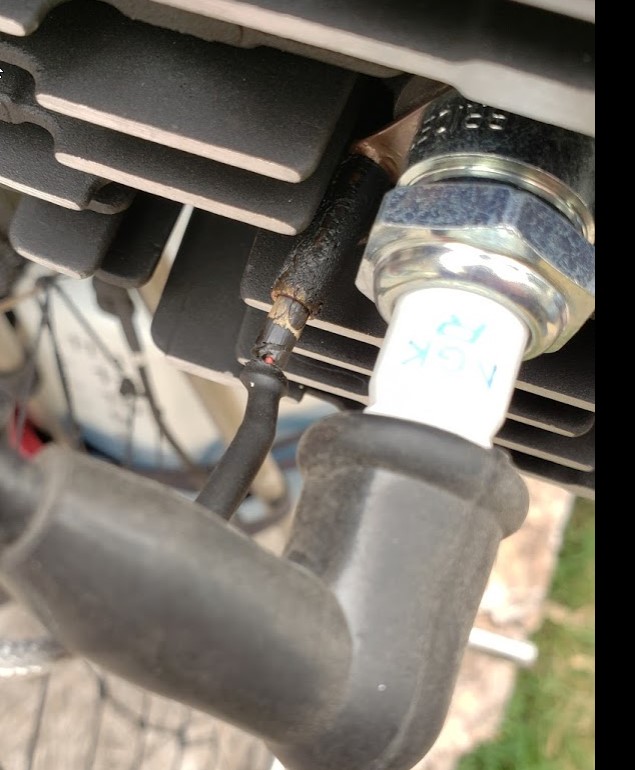
Some brands of gauges often cannot withstand the vibration found in paramotors and why we recommend that pilots purchase the TTO brand. Here's an example marketed by Gravity Paramotors. Their system does not use the expensive but durable "spaghetti wire" for the connection to the thermocouple. Also note the charred and failed shrink wrap around the sensor connection. Hopefully, they will get this fixed soon.
photos by Steve Dittmar
Installation
1. Parts and special tools needed 10mm or 14mm
- TTO Trail Tech Tachometer/Hour Meter Black #742-A00
- TTO Trail Tech Cylinder Head Temperature Meter Black 14mm Sensor #742-ET3 OR 10mm Sensor #742-ET1
- TTO Trail Tech Temp. sensor 24" extension lead #V300-24 (The extension MUST be used on the Top 80 and most other motors.)
- 4.5mm (3/16") wide black nylon zip ties (use commercial grade which is available in the electrical dept. at hardware stores)
- 3/8" or 1/2" heat shrinkable tubing (HST)
- #14 drill (11/64" or 4.5mm) or reamer to widen the mounting holes in the gauges
The TTO gauges and the CHT extension are available from Miniplane-USA.
2. Cooling air duct modification
Depending on the engine, the cooling air duct may have to be modified in order for the CHT sensor to be mounted underneath the spark plug. It must be modified while it is installed on the engine or the cut will not line up with the cooling fins on the cylinder head. There is just enough room between the fins for the sensor to fit. The Thor engines do not require any air duct modification but you will have to remove (or modify) the rubber seal that goes between the spark plug and the air duct.
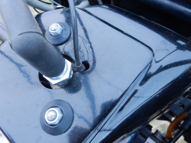
Remove the spark plug and cover the hole in the cylinder with a piece of masking tape. You do NOT want debris falling into the cylinder. Using a Dremel tool or a round file, make a cut in the duct by the spark plug 3/8" long and a width of the space between the fins, as shown in the photo. The cut is in line with the spark plug hole and perpendicular to the two duct mounting points. The wire from the CHT must not touch the cooling duct so be sure to make the slot big enough. It is better too big than too small. The CHT wire is delicate and should never be pulled tight at any point.
3. Gauge and sensor installation
The method used to mount the gauges are the same on any Miniplane frame. Other frames are similar.
a.) Mount the gauges Use nylon zip ties to mount the gauges on the left side bar. Do not drill holes in the side bar in order to mount the gauges because it could weaken important structural materials. A failure of the side bar while flying could be catastrophic.
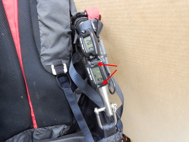
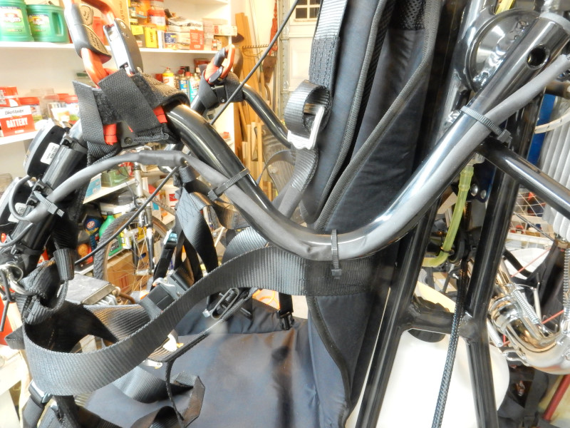
I have tried many locations. The location shown here is the best and will result in the least wear and tear on the sensor wires. Having anything on the throttle increases the risk of catching the throttle on the risers, glider lines, or straps. If you are having trouble in the air, you do not want the throttle to catch on anything. The gauges are also easily visible on the side bar. If they are mounted on the upper sticks, for example, you will have to turn your head quite a bit to read them. Mounted on the left side bar, it is easy to glance at the gauges without taking your eyes off where you are going.
The holes in the gauges are slightly smaller than the width of the ties. Smaller ties could be used but they are likely to break which is why the 4.5mm ties should be used. Use the drill bit or reamer to widen the holes in the gauge so that the ties will fit through the holes. If you drill the holes without using a drill press, be careful because the bit can snag the plastic and split it. A reamer works much better than a drill bit.
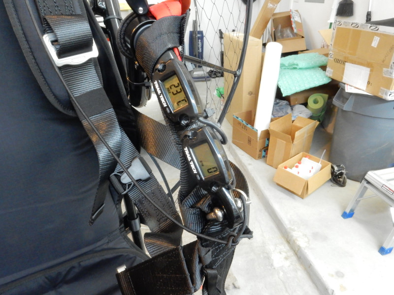
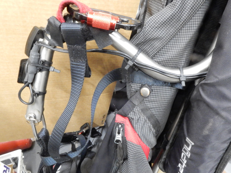
Typical installation on the left side bar of an Air Conception. The pilot of this engine supplied as with the gauges. The tachometer, however, was the "insert type" for pushing into a rectangular opening (red arrows). A drill press and reamer was used to make holes in the wings of the tachometer so it could be mounted properly. Never use black electrical tape to affix the gauge cables because this type of tape quickly smears black goo after it has sat a while.
Gauges installed on a Miniplane frame
b.) Attach the wiring A typical Miniplane frame, for example, requires about 17" of HST to enclose the gauge wires. They must be fished from both directions with a thin line. 4.5mm nylon zip ties can used to attach the sensor wires or HST assembly to the side bar as illustrated below up to the frame attachment point. If you use HST, it should not extend beyond the rear of the side bar. All wiring must have some slack to allow for flexing of the side bar.
3/8" HST was used here to protect the gauge connectors.
Note: the stock wire on the CHT is short so the (24)" extension must be used for some paramotors. The Minari and Air Conception have a horizontal engine so the extension is not needed.
This engine had HST installed over both gauge wires which is the best way because there is less chance of the wires being snagged.
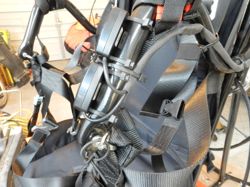
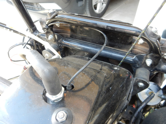
There must be a loop in the sensor wires (as shown) so they can flex with the up and down movement of the side bar. Stow the extra wire lengths in loops just below the side bar attachment point. The sensor wires are very durable but they cannot be stretched.
This installation does not have a full length piece of HST to cover the gauge wires. In case one of the gauges goes bad, it is easier to remove the faulty gauge if HST is not used to cover both wires.
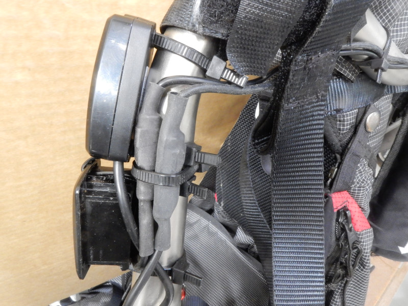
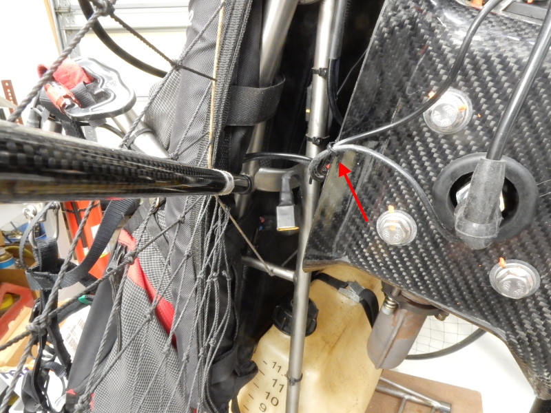
c.) Tachometer sensor wire location The RED tachometer sensor wire may be shortened as needed and loosely wound around the secondary (spark plug) wire 3 or 4 turns. If you wind the pickup wire with too many turns it will overload the circuitry in the gauge and the gauge may give erratic data. The red sensor wire can be secured with a bag tie, as here, but this is not necessary. The tachometer electronics are very sensitive and will always pick up the spark. Wrap the wire around itself, as illustrated in the following photos. The excess tachometer wire and the excess CHT extension wire can be secured to the frame with nylon zip ties. Option: the tachometer wire can be cut to fit and the black outer covering stripped off for a neater installation. The CHT wire, however, cannot be shortened.
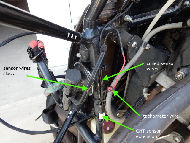
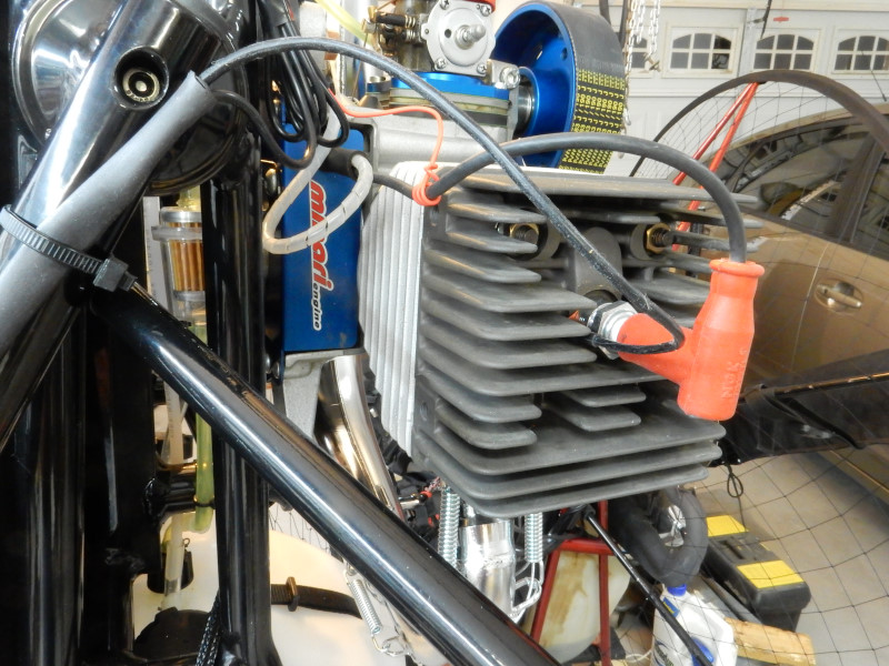
In the following photo, the gauge wires were secured the cooling shroud by a small zip tie. Always have a small loop between the engine and where the wires are connected to the side bar.
d.) CHT sensor installation Remove the existing spark plug. Do not remove the metal gasket on the spark plug because it help prevent the CHT sensor from getting chewed up by the base of the spark plug. Some engines have a 2-3mm thick copper or aluminum spacer washer on the spark plug in addition to the stock gasket that is on all spark plugs. Remove the spacer washer, if there is one, and put it aside for the moment.
Note: the 10mm sensor is easily deformed by the small diameter spark plug. Install a 10mm flat aluminum washer between the spark plug and the sensor. If needed, pilots may contact us to order these washers ($1 + free shipping).
NOTE: SOME CYLINDER HEADS (MINARI) HAVE SPARK PLUG HOLE SURFACES THAT ARE NOT FLUSH. THE SENSOR MUST BE ORIENTED SO THAT THE FLAT AREA OF THE SENSOR ENTIRELY CONTACTS THE FLAT AREA AROUND THE SPARK PLUG HOLE. The Minari must have the sensor at the 8 or 9 o'clock position.
e.) Spark plug reinstallation Put the CHT sensor on the spark plug and then the spacer washer, if there is one.
While tightening the spark plug, hold the sensor so it does not touch any parts of the air duct (if there is one) or the cylinder at any point. Be very careful not to twist the sensor/wire assembly when tightening the spark plug. Always use a torque wrench to tighten the spark plug to specifications.
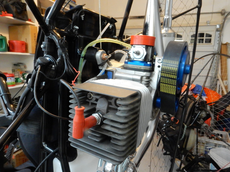
The completed installation should look like this on a Top 80. Other engines are similar.
4. Testing
Check your owner's manual for the maximum operating engine temperature. Get used to glancing at the CHT often. You will get an idea of how your engine operates in various conditions, which is important!
The CHT can be setup with either Fahrenheit or centigrade. I recommend using centigrade because all paramotor engines are manufactured outside the U.S. and the temperatures specified are always given in centigrade. Someday, the U.S. will abandon the antiquated, difficult to use English system of measurement and fully adopt the metric. I am not optimistic that it will be soon....
![]()